Can I combine voltage dividers and caps for multiple CT circuits?

I am designing a circuit that uses 8 CTs being read through an analog switch. I was wondering if I could just combine the voltage dividers (using lower R values) and the capacitor (using something like ~80uF for all 8).

I looked in the schematics and this isn’t done. I can’t figure why it hasn’t been done. It would save a bunch of components. If it hasn’t been tried, I will go ahead and give it a shot and compare the results.

Thanks!

Yes, it has been done. Robin Emley uses an op.amp. buffer, and it’s documented somewhere in Resources, or in a post on the old forums.

What you need to watch out for, is there’s enough stability in the bias supply so that a reading is not influenced by the previous one being read. It’s the charge on the capacitor, or the current from the op.amp, that charges the sample & hold capacitor inside the ADC.

Here is the thread that I started on the old forum about sharing the voltage reference between several circuits. Sharing the 2.5V reference | Archived Forum

Without an active element in the reference circuit, I was seeing crosstalk between the channels. Once the op amp buffer was introduced, all such effects went away.

1 Like

Thanks for the link @calypso_rae. That helps a lot. So it looks like I don’t need a cap if I use the op amp. Is that correct?

Is it still considered best practice to use suppression diodes on each line? Right now, I have an inline 100 ohm resistor between the CT and the analog pin.

I have never seen any need for a capacitor at the input of the op-amp. The voltage here marks the mid-point of the ADC’s input range, i.e. Vcc/2. AC-coupling it to only one of the power rails doesn’t make any sense to me when the op-amp buffer is present.

The Atmega inputs are very rugged. If extra diodes are added, there is no guarantee that they will conduct first to divert current away from the internal protection. A series 100R resistor at each CT input makes good sense. One of my own PCBs has this extra precaution.

[Edit - sorry, the series resistor that I use for this purpose is 1K0 rather than 100R]

.

1 Like

There’s been a lot of discussion about that. The short answer is, nobody has reported a failure when suppression/clamping diodes have not been used, but you much reduce the possibility of damaging the input if they are present, together with an appropriate current-limiting resistor. 100 Ω will help a little, but as the internal protection diodes have very limited current-carrying capacity - 1 mA according to some sources, it probably won’t be enough. But you mustn’t go above 10 kΩ or accuracy will be affected. You should find most of the discussion in the old forums, I think.

1 Like

Thanks for your input @calypso_rae and @Robert.Wall! I am finalizing my board design and we’ll see how this goes.

(This is my first post, which I’m making in reply to this topic, since it’s closely related – but please let me know if I should break this out into its own topic.)

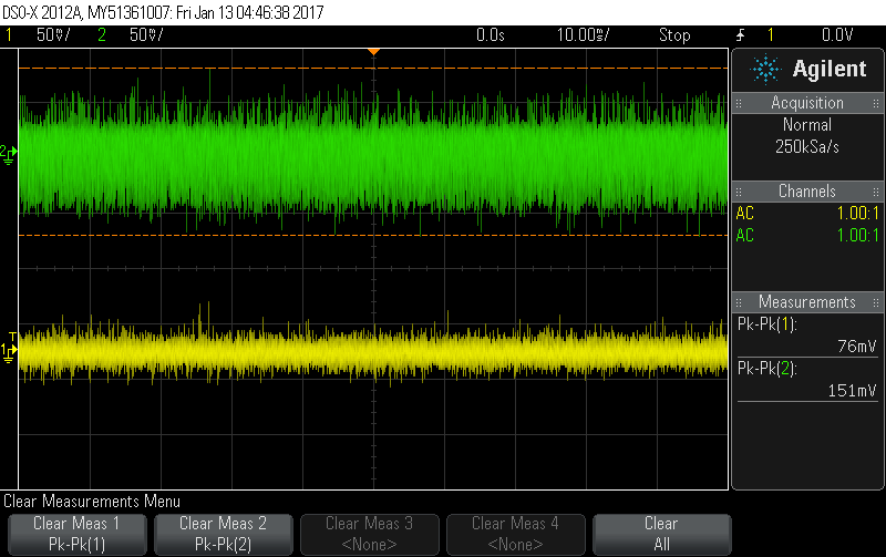
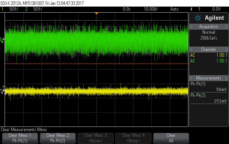
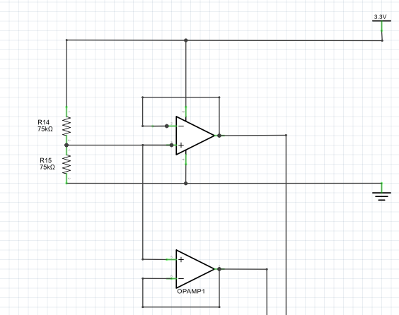
I’m currently designing shield for an Arduino Due that will allow for 11 CTs to be monitored. I’ve used the op-amp solution that Robin proposed in the old forum in order to provide more stability and save space on my PCB. The IC I use has two op-amps in it – 6 of the sensor currents are biased by one and 5 of them plus the voltage sensor by the other. Both appear to have a steady output of 1.65V when I measure them with my voltmeter.

I’ve had a bit of a hiccup, however. After calibrating my for YHDC SCT-013 CTs (a variety of 15A/1V, 20A/1V, and 50A/1V), I noticed that the no-load current values were rather high – higher than the unavoidable “noise” I’ve read about on these forums.
Here are readings I pulled off the Arduino IDE serial monitor (though in the past these current numbers have been twice as high --I don’t know why):

121.70 V
CT1 (15A): 0.17 A, 21.19 VA, -7.14 W.
CT2 (15A): 0.14 A, 17.52 VA, -5.84 W.
CT3 (15A): 0.15 A, 17.63 VA, -2.34 W.
CT4 (15A): 0.15 A, 18.34 VA, -7.43 W.
CT5 (15A): 0.15 A, 17.96 VA, -5.34 W.
CT6 (15A): 0.15 A, 18.36 VA, -7.16 W.
CT7 (15A): 0.15 A, 18.03 VA, 2.14 W.
CT8 (20A): 0.19 A, 23.08 VA, -4.82 W.
CT9 (20A): 0.20 A, 23.91 VA, -4.28 W.
CT10 (50A): 0.47 A, 57.66 VA, -9.33 W.
CT11 (50A): 0.54 A, 65.12 VA, -24.86 W.

(Here is the sketch i’m using: BemonDue_DirectSerial_forCalibration.ino (5.9 KB))

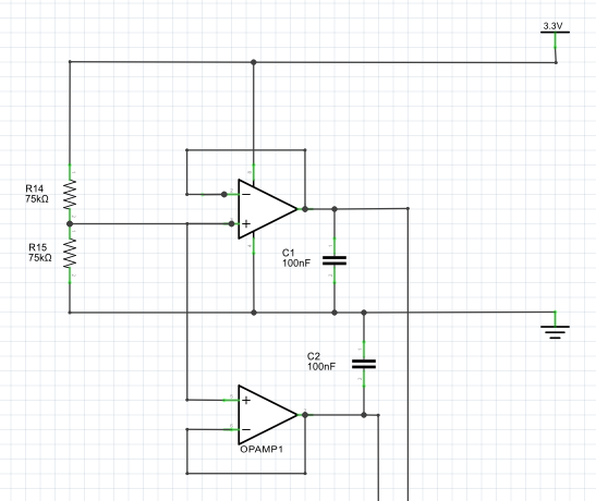
I found another topic on the old forum, where Robert suggested adding a 100nF capacitor between the op-amp output and ground if the current at no-load is too high. So I added a couple of these.

This brought the no-load current readings down – and made the power readings more reasonable:

121.63 V
CT1 (15A): 0.02 A, 2.86 VA, 0.20 W.
CT2 (15A): 0.02 A, 2.70 VA, 0.56 W.
CT3 (15A): 0.04 A, 4.56 VA, 2.90 W.
CT4 (15A): 0.03 A, 4.15 VA, 0.56 W.
CT5 (15A): 0.04 A, 4.27 VA, 0.58 W.
CT6 (15A): 0.04 A, 4.68 VA, 0.50 W.
CT7 (15A): 0.06 A, 7.88 VA, 6.30 W.
CT8 (20A): 0.06 A, 7.83 VA, 3.44 W.
CT9 (20A): 0.06 A, 7.45 VA, 3.68 W.
CT10 (50A): 0.14 A, 17.06 VA, 9.72 W.
CT11 (50A): 0.12 A, 14.56 VA, 1.58 W.

But here’s the twist: it only solves the problem if I add the capacitors while the sketch is running.
If I power up the system with the capacitors already in place, the current for each CT is once again too high (and in fact much higher than starting the system without the capacitors):

119.73 V
CT1 (15A): 0.75 A, 90.09 VA, 13.26 W.
CT2 (15A): 0.75 A, 89.74 VA, 4.94 W.
CT3 (15A): 0.74 A, 88.29 VA, 6.88 W.
CT4 (15A): 0.75 A, 90.00 VA, 25.69 W.
CT5 (15A): 0.75 A, 89.46 VA, -1.08 W.
CT6 (15A): 0.76 A, 90.59 VA, 9.46 W.
CT7 (15A): 0.75 A, 89.12 VA, 15.95 W.
CT8 (20A): 1.01 A, 119.96 VA, 16.93 W.
CT9 (20A): 0.98 A, 116.74 VA, 17.89 W.
CT10 (50A): 2.50 A, 298.80 VA, -0.98 W.
CT11 (50A): 2.44 A, 290.80 VA, 41.48 W.

Removing the caps drops the calculated currents, though not quite to the levels that come from adding capacitors after system start-up:

121.67 V
CT1 (15A): 0.13 A, 15.41 VA, -7.58 W.
CT2 (15A): 0.08 A, 10.26 VA, -5.90 W.
CT3 (15A): 0.08 A, 9.81 VA, -2.02 W.
CT4 (15A): 0.09 A, 11.18 VA, -7.26 W.
CT5 (15A): 0.09 A, 11.44 VA, -4.79 W.
CT6 (15A): 0.09 A, 10.79 VA, -6.84 W.
CT7 (15A): 0.08 A, 10.15 VA, 2.92 W.
CT8 (20A): 0.10 A, 12.06 VA, -4.52 W.
CT9 (20A): 0.13 A, 15.73 VA, -3.40 W.
CT10 (50A): 0.24 A, 28.90 VA, -7.74 W.
CT11 (50A): 0.35 A, 43.08 VA, -23.86 W.

I’m not very clear on what the capacitors are doing. Would anyone be able to explain that? Any ideas on why I need to add the caps after I’ve turned my system on? And any ideas on how to resolve this issue so that I can have all my components permanently connected? I’m going to experiment with some caps of different sizes, though my inventory is a little limited.

The purpose of those capacitors is to kill any h.f. noise or oscillation on the output. But from your description, it sounds as if you’ve made an oscillator that starts up from power-on, but doesn’t when you add the capacitors afterwards. The data sheet for the op.amp. that you’re using might offer some advice about its ability to drive a capacitive load, hence the maximum value of capacitance that you should have. I presume you don’t have access to an oscilloscope to find out exactly what’s going on.

One other suggestion is that your library isn’t removing the d.c. offset as it should. I’ve no idea what if anything you’ve changed, so that’s really only a guess.

(And note: As far as I know, emoncms.org won’t accept posts faster than 10 s, not 5 s as your comment suggests.)

Thanks for the advice, Robert. I can arrange for access to an oscilloscope, so that will help me figure out this issue.
In the mean time, I tried out a 20nF and a 10nF capacitor. Both have the same positive effect on my readings as the 100nF capacitor, but they can be added to the circuit before it is turned on.

I think your op.amp. is oscillating. Is it a particularly high performance one, and have you followed the pcb layout for it that the data sheet recommends? It may well be that the op.amp. requires some local supply decoupling.

I’m using the LM258A opamp from Fairchild (datasheet: LM258A-opamp.pdf (156.0 KB)). I’m not certain what constitutes a high-performance op amp (my understanding of op amps is pretty basic). I chose this device mainly because it needs only a single power supply and its power input and output characteristics meet my needs (I’m powering it with the 3.3V pin on my Arduino and need it to output 1.65V).

I’m not able to find anything in the datasheet about PCB layout (I’m still working on a breadboard though). I’ll look into local supply decoupling.

Thanks again.

The LMV358, the low voltage single supply version, has been used in the past, and I think that’s what was specified originally. You might be having problems because the supply voltage is very low for the LM358, even though it is specified down to 3 V.

The issue of the ‘no-load current’ has bothered me for some time now and I’ve gone to several other forums to discuss it and have not been able to resolve it. I am meeting with someone in the next couple weeks to help me troubleshoot it with an oscilloscope.

What I’ve found is that the power source drastically affects the readings. If I use my Macbook to power it, I get 0.03A reading at no-load. If I use a cell phone charger, I get around 0.3A, but if I switch to a dc barrel jack with a 5V wall wart, I get up to 0.7A. My uC is 5v.

I thought it had to do with ground, but I’ve tested connecting ground to earth ground, and get no change at all.

Also, I get this result using an Arduino Pro Mini, a through hole PCB and an SMT PCB. All get the exact same readings, so I doubt that it is the layout.

At any rate, I’ll post again once I use the oscilloscope.

If you search, you’ll find many mentions of noise, including a discussion of the merits of the various Arduino power sources.

I finally was able to use an oscilloscope. My 3.3V and 5V regulated supplies on the Arduino both seem kind of noisy, as does the op-amp output. I don’t think this is normal.

(Channel 1 is the op-amp output, Channel 2 is the 5V pin on the Arduino)

Adding a 100nF capacitor to the output of the op-amp dropped the noise down a bit.


I found that the times when the op-amp doesn’t seem to work coincides with a high-pitched squeal coming form the Arduino. This happened once when I was hooked up to the scope (I wasn’t able to get a screen shot) and there was a ton of noise on the op-amp output. In other words, the current readings are not thrown off simply because the caps are there when I turn everything on. Something is randomly happening in the Arduino (thinking back I noticed this squeal the first time I connected this particular Arduino to my computer). I may purchase another one, but in the mean time, I’m content with just paying attention to the squeal on power-up and restarting everything if I hear it.

I powered my op-amp with an external DC supply at around 9V and didn’t see any improvement in the op-amp’s output.

The squeal from the Arduino is worrying. It could mean that you are shorting something - and consequently damaged something - by connecting two places that shouldn’t be connected together. Is your computer earthed (if you have a 3-core mains lead, it probably is), is the 'scope earthed (it should be) .

With 150 mV p-p of noise on a 5 V supply, I’m not surprised you have problems. I see about 50 mV p-p on an emonTx running off my laptop.

My computer and the scope are earthed.

Do you suspect the voltage regulator in the Arduino could have been damaged by whatever is causing the squealing, and that that is causing the noise on the supply? (note I mislabelled the scope channels in my last post – Channel 1 is the op-amp output, 2 is the 5V pin).

I don’t know the details of the Arduino, so I cannot be certain - especially by remote control! But you do need to check the voltages between the various earths, it’s a common problem when you are connecting multiple items together.

Have you looked at the Arduino 5 V with everything that it’s possible to disconnect, including your op.amp etc, totally disconnected? If it’s rubbish then, you’re going to struggle to use the analogue inputs to measure anything much less than half a volt.

Also, try looking at the raw power without the Arduino (but if you can rustle up a resistor load that takes roughly the same current as the Arduino, with that connected. You should soon see whether it is the power supply or the Arduino that’s the source of the noise.

This is a 3.3V Due right? Where is the 5V coming from? Is the 5V used for anything? Does the 3.3V rail look just as noisy? Do they look better if you power it via the DC-IN jack (assuming you’re currently powering it via USB).