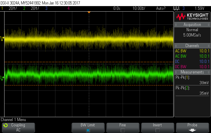
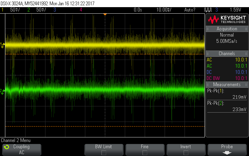
You might want to consider enabling the 20MHz BW limit on the probes. The peak-to-peak measurement includes all those fine high frequency whiskers. Without that filter, my 200MHz scope sees a lot more noise (note the different y-scale as well):
That high frequency stuff probably doesn’t matter much. It’s probably too fast to impact on your readings, and depending how you’re probing, it may not be real anyway, i.e. it may be pick-up in the Arduino patch cables rather then exist in the actual signal.
Having said that, your Green trace is quite “thick” compared to mine. It’s not just the odd whisker that’s giving you a big reading which suggests your noise is fairly low frequency, so the BW Limit may not make much difference.
I’ll take a closer look at the Arduino itself disconnected from my system and at the power supply once I have access to the scope again. Thanks for the suggestions on what to look for Robert.
I’ve usually been powering the Arduino through the DC-IN jack with a 9VDC wall wart. I’ve checked my sketch’s output results while powered with a 12V battery and with the 5V USB supply and they are the same. Does this suggest my Arduino is having problems properly regulating the supply? In other words, if it was working properly, I wouldn’t need any filtering in my system?
Thanks @dBC for providing the scope screens for comparison. I had tried powering my op-amp with the 5V rail of the Due to see if that gave better results (3.3V is close to my op-amp’s minimum input power).
I’ll update once I have investigated more with the oscilloscope.
It looks like the 9VDC adapter I’m using to power my Arduino is pretty noisy. I’m not able to get any screen captures off of the oscilloscope, but it’s producing a signal similar to what I have shown in my scope screens in a previous post. It’s producing a peak-to-peak voltage of about 140mV.
When the Arduino is powered through USB, the 5V pin --disconnected from my breadboarded circuit – is still higher than what dBC showed in his scope screens. It’s producing about 90mV peak to peak.
I will try another power supply on the DC-in jack and see if that helps.
That is interesting. I can’t say I’ve ever checked on a Due, but on traditional AVR based Arduinos, that DC-in jack was usually the best way to get a clean 5V rail. All the ones I’ve looked at use regulators that are very good at rejecting noise on the DC-in jack, whereas when you power them via USB 5V they usually have nothing in the circuit and you’re at the mercy of whatever is at the other end of the USB cable.
When I get a chance I’ll power up my Due via the DC-in jack and see how it looks.
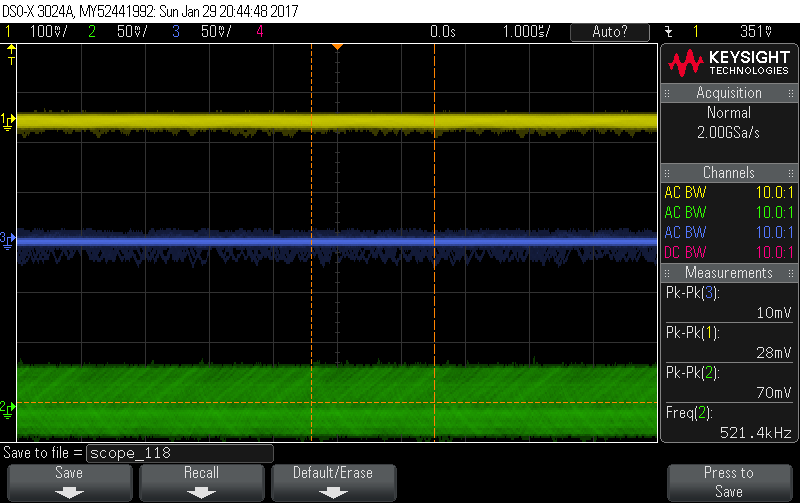
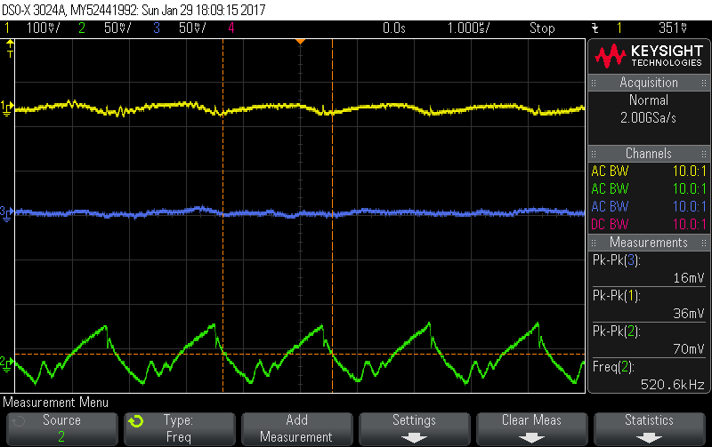
OK, I finally got around to doing that homework assignment I set myself. The attached pics are from my Due being powered by a 9V wall-wart via the DC-in jack.
(Yellow) is the ~9V Vin from the wall-wart
(Green) is the 5V rail
(Blue) is the 3.3V rail
Looks like the moral of the story is you want to stay away from that 5V rail for anything ADC related. They use a DC-DC buck converter to generate it and you can see it’s very ripply. But they use a linear regulator for the 3.3V and it’s pretty clean.
Ouch!
Not knowing anything much about Arduinos, are they all created equal, or is there likely to be a variation between boards from different manufacturers?
Actually, that was measured on an official Arduino Due. I’m not sure if the clone market ever got into full swing with the ARM-based Due. Keep in mind though the Due is an entirely 3.3V only system. I’m not even sure why they generate a 5V rail, maybe to power external stuff? At any rate it looks like it’s not suitable for anything that ends up near the ADC inputs.
To answer your question though, at least on the AVR side of things (i.e. not the Due) I think there are clones and there are clones. The simplest of clones simply download all the design files and hit “print” so I’d expect them to be pretty close. Others “add value” by improving things, especially the power supply stuff, so then it comes down to how well they know their trade.
Thanks for taking the time to investigate this. It may be partly that my oscilloscope skills aren’t that advanced, but as I mentioned before my 3.3V and 5V rails don’t look anything like that. I recently found another DC adapter that I’m going to try on my system and try and get some 'scope captures.
I’m glad to learn that the 5V rail shouldn’t be used with the ADC.