Hello, I have 0 experience.
I am working on a project to measure current across all of my homes circuits (that feeding the over, the lights, the garage door etc.) I only want to tell whether the power is on/off, so that I can automatically detect an outage on a circuit.
I have the impression that to do this I will need to attach a CT to every single circuit?
Given that the maximum CT clamps you can attach is 4 I thought this might not be feasible?
Could someone tell me if I can get this function to work with just 2CT and an Emon device?
A CT will not necessarily detect an outage, unless used on a circuit that always draws current. The CT will only indicate the level of current and from that the power is determined, a circuit that is switched off but still live will appear the same as a circuit during a power outage ie 0 amps 0 power.
It is the voltage that you need to detect for recognising an outage. The emonTx does have an AC detection circuit, so you could sense a single AC circuit, although you are limited to those circuits that have sockets to accomadate your wall wart unless you use another sensor style (eg hardwired component transformer.). With the emonTx, you then have to look at an alternative battery or UPS 5v power supply because it gets it’s power from the AC:AC adatpter usually. So when the circuit in question is not powered, the emontx will not be able to report that unless there is an alternative power source.
There have been various other ways of sensing if a circuit is simply on or off here on the forums (mainly the archived forums IIRC), my favourite is simply to use a mains neon and a light sensor taped together, this gives you a level of isolation, mandatory when sensing mains AC.
And that, when combined with an Arduino with multiple inputs (therefore not an emonTx), would allow you to monitor many individual circuits very cheaply.
But Paul’s point about power is important: If power to your monitoring device fails, you will never know about it.
Ah wow right I hadn’t even thought of that.
If it’s not too much to ask, could you help me understand what hardware I’ll need to achieve my goal? “Identifying outages on an electrical circuit.”
I’d like to identify this outage not on the mains but the individual circuit the problem has occurred on.
I did not quite understand whether the EmonTx would be the best choice? Especially given Roberts comment below.
I’d be glad to get in touch via e-mail too! As this is pretty hard for me to get my head around haha
I think an emonTx is probably a poor choice - but we shall see.
What you need to do first is decide what you actually want to achieve.
So:
What is an outage? Is it a blown fuse or a tripped circuit breaker that you are worried about?
How long must the outage last before you want to know about it?
How many circuits do you want to monitor? Do they all come together at the same place, e.g. are they outgoing ways from your distribution board?
We prefer not to do that. It might be the case that someone at some time in the future wants to do exactly the same thing, then they can search for and read this thread, and they will be very happy (we hope).
Great. And good thought on the thread.
So update:
I want to know whether a circuit breaker / differential circuit breaker is in ON or OFF mode.
I want to know this for every circuit inside my distribution board.
I’d like to identify why the breaker turns off (but that’s not a priority right now; all input is much appreciated)
I am thinking of using the following set up:
Attach a Magnetic Probe Tip to each breaker to see whether there is tension
Attach all probes to the Arduino (applying a resistance that brings down my voltage)
When there is no tension on a circuit, have the Arduino trigger a notification for it.
I’m still unsure whether this setup will be practical, given that it’ll require close to or more than 20 Probes and hence a lot of wiring.
For your personal safety, you cannot connect your Arduino or any other electronic device directly to mains electricity. You MUST use something like the neon lamp and light sensor so that there is no direct electrical connection, as Paul (pb66) said. The cost in money is small. If you do not do as we recommend, it could cost you your life, or the life of one of your family.
"I’d like to identify why the breaker turns off"
If you are using the voltage, you will never know whether someone has turned it off or whether it has tripped. You must continuously measure current, most likely for every breaker, in order to know that. When the voltage disappears, you must analyse the current for a period of time - tens of seconds - before the trip to determine whether it was a continuous overload - meaning the breaker was tripped by the thermal element, or whether it was an instantaneous overcurrent - meaning the breaker was tripped by the magnetic element. This will mean a current transformer on every circuit and some very clever software, and that means a processor with at least one analogue input for each circuit. In reality that means at least two of the most powerful Arduinos, because you must continuously measure the current in all 16 inputs. Our emonTx/Arduino Uno can only measure 4 currents plus one voltage - 5 in all. If you try to connect any more, it will not run fast enough to measure the current in a short circuit before the breaker trips.
For a processor, I think you need an Arduino Mega or Arduino Due. Those have enough Digital I/O pins for many more than 20 circuits.
In your software, you will need to scan every sensor input at least 200 times per second, and if the light is off for more than 20 ms continuously, then you can say the breaker is open.
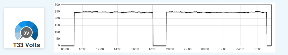
I had a similar problem to solve and happened across a different solution, although it’s a bit bespoke to my setup and may not work for yours. We have a tariff here known as “T33 - Controlled Load”. The grid manager remotely turns that meter on/off throughout the day to help balance their peak loads. Loads connected to that meter must be hardwired so you can’t game the system by just plugging it in elsewhere when they turn it off. It’s ideal for loads that you don’t much care when in the day they run. From memory I think they guarantee it will be powered for at least 18 hours per day and they rarely change the run times from day to day - only during grid emergencies, and perhaps twice a year to change between winter and summer settings. I’ve got my pool and hotwater (mostly solar thermal) boost connected to it.
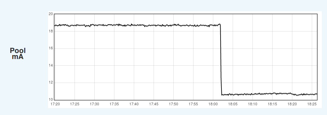
I wanted to log when it was energised, mostly so I could program the pool timer around it but there was no easy way to directly measure the voltage. It turns out the first component in the pool plant (hardwired as per the regulations) is a small thermal safety cutout box with a green LED to show when it’s operating normally. That box draws just enough current that I can use it to determine when the meter is energised:
So if you have enough always-on devices on your circuits of interest, and they’re reactive enough even when not being used, you may be able to deduce whether the circuit is energised by looking at the Irms reading.
Safety instructions are very much appreciated!
I’ve gotten a bit confused, since you mentioned earlier that if I just measure current I won’t be able to tell if the breaker is off or that there just isn’t any power being drawn?
If I’ve understood you right you recommend measuring current on each breaker as well as voltage, and using those two inputs to determine what the cause of the breaker OFF position is?
Is there a way to do this with one sensor? Or will I need two different ones?
As for the Arduino Mega, I didn’t understand your point about “whether it would do analogue currents as well”. I thought I could attach either a current or voltage sensor to the DOI and have the analogue input translated to digital by the ADC?
Yes, that is exactly right. If there is a break in the circuit anywhere - either a control switch or the breaker, no current will flow. All you know then is there is no current, you have no means to find out why.
Yes. Voltage will tell you if the breaker is open or closed. Current before the breaker opens should normally give you an indication why. (E.g, zero current immediately before the breaker opens means a manual opening.)
No, you need both, if you want to know why.
There might not be enough power in the processor to do both tasks. The Due is much more powerful and I think that would be able to carry out both tasks - but if you want to measure the current on each circuit, you will need two. Measuring current on many circuits simultaneously and sampling quickly enough to catch and analyse a fault will require a lot of processing power. But I’m not an Arduino expert, so I could be wrong.
Okay great. Very happy with the response format, super clear.
So:
To sense current I should take a CT clamp?
To sense voltage I should take …?
The CT clamp will connect to my breaker phase and have two wires, I’ll connect them each to an Arduino DOI?
The voltage “sensor” will connect to … and have two wires? and I’ll connect them each to an Arduino DOI?
What @pb66 Paul suggested - a neon lamp and a photo-receptor. Hopefully, he’ll be along and give you the components he used, and how to wire it.
(I know how I’d do it, but as he’s done it and it works, why re-invent it?)
I read about it many many moons ago and tried it out a couple of years ago for a specific test, I actually used short pieces of rubber hose and pushed the neon and LDR into each end, I think the article I read used a cut up Bic pen body IIRC. If I did it again I would probably just use a ridged heat shrink tubing to hold the neon and LDR, that way it could be a pretty tidy device with just 2 wires hanging out each end of a piece of heat shrink tubing.
As for the components, I just used a neon I had kicking around and ordered a LDR off ebay. At the time I used a ADC input so it was fairly adjustable in software, next time I would probably play with the pull-up/down resister and try and get a output level that can be read directly by a digital input.
I think you would probably be far better informed about what are the correct component values, I would resort to a bit of web searching mixed in with a bit of trial and error if I had too. The only thing that immediately springs to mind is get the lowest power neons you can, a handful of them running 24/7/365 can add up, most common are 250mW but I’ve seen some readily available 120mW so that halves the consumption (and heat) straight off.
The test circuit I did previously was actually wired across switch terms to report the switch activity using the line feed to the switch and finding a path to neutral via the load, so the neon was only lit when the switch was off, that approach probably cannot work in this instance since the load would need to be permanently connected and switched on to provide a path to neutral if the CB is tripped or manually switched off. If the circuits had reliably permanent loads then a simple CT would suffice and no neon+ldr would be needed, so it has to be assumed that all neons will be lit permanently unless there is a fault condition (open CB).
I just did a quick bit of searching and found these to start with
you could probably get away with a 0.125W but perminantly in use and wrapped in heatshrink, I would stick with 0.25W and metal film have a more stable temp coefficient ?
As for the pull-up/down resister I would need to read up or resort to trial and error (or both!) to try and get the switching level right for a DIO (and that value would be different for a 3V3 or 5V MCU too), but I would again go for a more stable type of resistor if mounting within the heat shrink, we don’t want false triggers due to temperature changes and resisters are so cheap you don’t need cheap resisters.
That’s very much what I had in mind. But my real hope was that you had known-to-work component part numbers and values. I’ll try to work out how much light you get out of a neon, but I rather think it’s got to be trial and error, and it’s going to be heavily dependent on how the neon lamp and LDR come together. End-on - not so much, maybe white sleeving could be used inside the heat-shrink tubing?
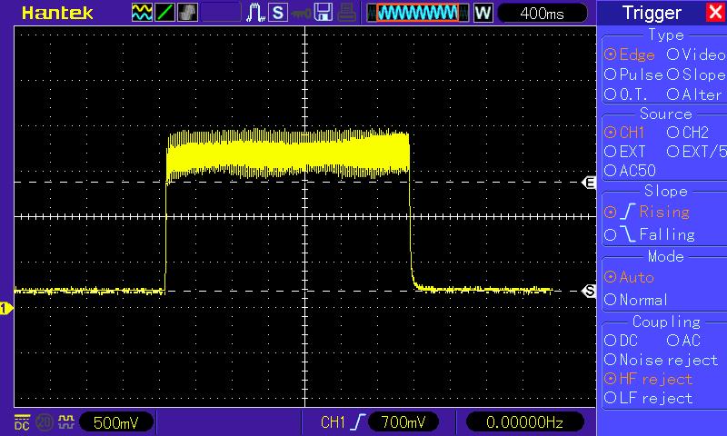
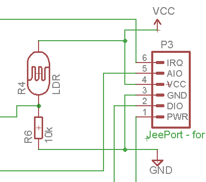
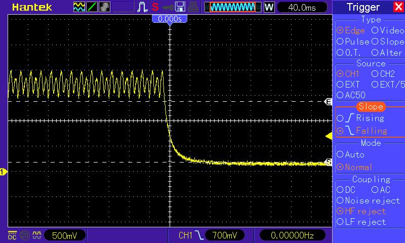
Not having either of the components @pb66 mentioned, I used the first neon lamp I came across (it happened to have a 680 kΩ series resistor attached) and the LDR in an emonGLCD.
With those two coupled together by a tube of Blu-tack (the CdS cell looking at the end of the neon), I got this picture:
The highest ‘dark’ or ‘off’ voltage [S] is 180 mV, or 0.054VCC;
the lowest ‘light’ or ‘on’ voltage [E] is 1.38 V, or 0.418VCC.
In the emonGLCD, the series resistor is 10 kΩ:
That means that the ‘light’ resistance ≈ 14 kΩ, and the ‘dark’ resistance ≈ 173 kΩ.
The 10 kΩ series resistor is clearly too low in value for this application - the Atmel data sheet (for the '328P) gives the lowest voltage guaranteed to be seen as a logic ‘high’ as 0.6 VCC.
By my calculations, for this application the series resistor needs to be at least 24 kΩ, I’d suggest 27 kΩ, but no higher than 33 kΩ, because the maximum voltage guaranteed to be recognised as a logic ‘low’ is 0.2VCC and 33 kΩ should give about 0.16 VCC ‘dark’.
The CdS cell has quite a slow response, which makes the software a lot simpler - there’s no need to check every half-cycle of the mains, the input can be checked a quickly or as slowly as you wish.
I hadn’t really thought about it much when I first tested it, and when it worked had no reason to question it, but yes, end on might not be the brightest idea But I do like the “2 wires hanging out each end” approach to keep things safe and easy to understand the arrangement.
The neon I used was just pulled from a fused spur type switch so I have no idea what value it was or how bright it is compared to others.
My thought on the “tube” was that there was no where else for the light to go and zero chance of any ambient light.
Good idea, white would aid directing the light to the LDR, you can get stiff white heatshrink sleeve so it can possibly still be done in one layer.
I found the same thing, IIRC I just checked it once before sending (every 5-10s?).
If it’s “Sparkfun” there should be oodles of blogs, posts and guides on using it in different scenarios I would of thought?
Quite so - that’s how I set it up, and as I got meaningful results I didn’t try any other way, for exactly the same reasons.
But no credible data sheet that I could find, so we’ve no idea how far individual devices might deviate from the value I measured, or indeed how representative the one I measured is. It would seem that “select on test” for the resistor will be the only guaranteed method using that device.