I found the Sparkfun sheet, didn’t spot the link to the other ones
Better late than never 
Back when we had this discussion I ordered some low power neons with the intention of experimenting, the only experiment they have been involved in to date is to determine how much dust they can gather in my garage.
With an upcoming project needing something to report when certain mains powered circuits are live, I decided to try a simple high low type sensor for a digital input and have had some success with this.
Initially I tried an offcut of outer sheath of a bit of coaxial tv antenna cable with the neon in one end and the LDR in the other so they were end to end with a gap. This first trial wasn’t looking good when the “off” resistance was a meg or 2 and the “on” was 5-6kohm, yes I could of probably got it working, this is possibly close to the ADC based previous implementation, it worked after playing with the calibration.
Wanting a simpler sensor, I tried laying a heavy cloth over them to reduce ambient light and hopefully stop light entering via the glass neon when it was off, that certainly improved the “off” resistance close to open-circuit, but the “on” resistance was unchanged at 5-6k, I wanted to use nothing more than the in-built pull-ups in the Pi’s GPIO so I had to improve the brightness seen by the LDR, before starting to meddle with the recommended series resister value for the neon (330k) I tried some white heat shrink as we discussed above (the coax sheath was brown) and moved the neon and LDR closer together, still end to end to make packaging this up easily done with heatshrink.
This took the “on” resistance down to 2k, the heatshrink hadn’t been shrunk at this point and there was just the one layer. Happy with this I put it all together on a short bit of main’s 2-core flex and a couple of bread board type patch wires.
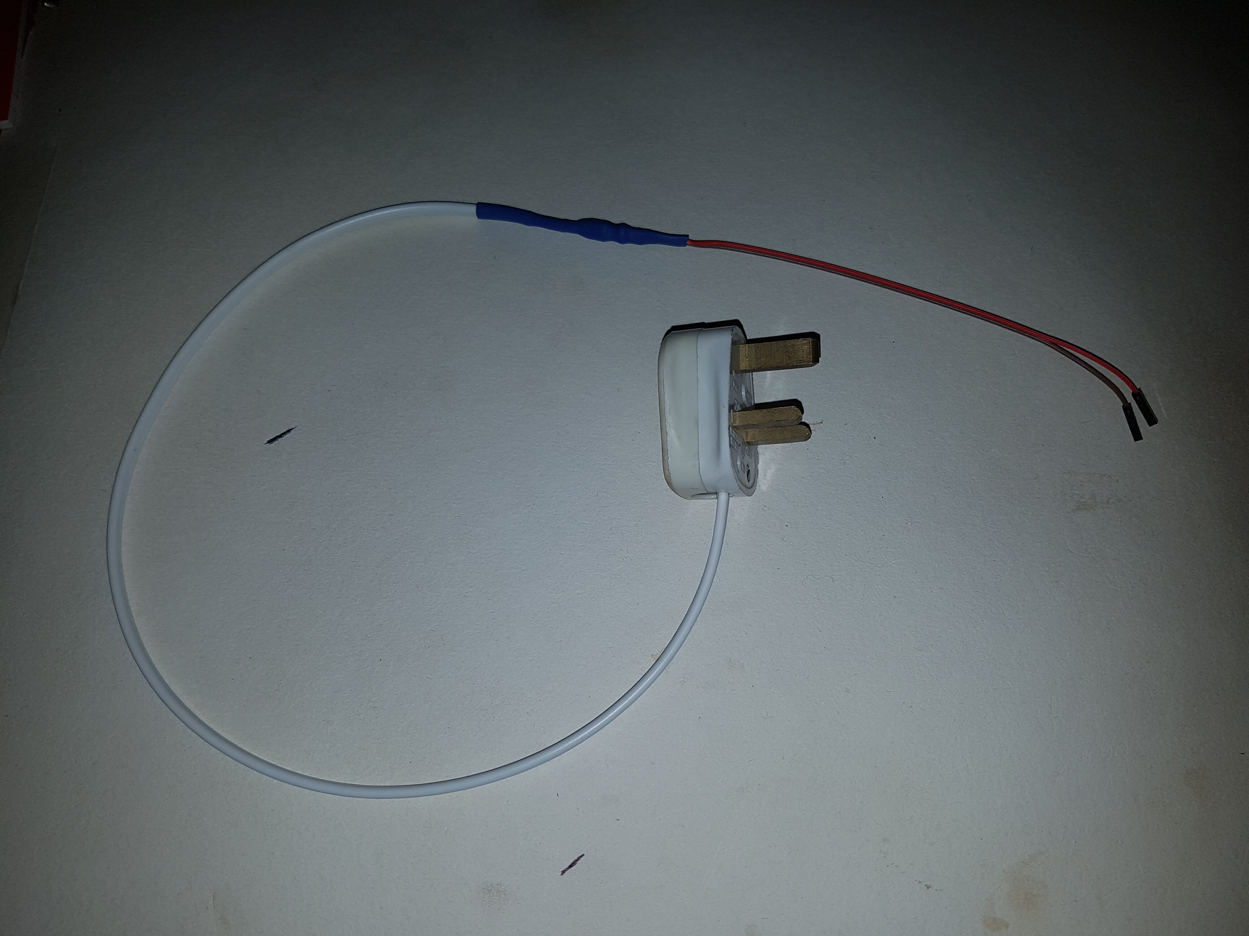
Using a TP-link hs110 smart plug to switch the mains on and off via an android app, I measured open-circuit “off” and 1.8k “on”.
connecting the 2 wires to a RPi pins 37 (gpio26) and 39 (ground) and wrote this quick script to test
import RPi.GPIO as GPIO
import time

# We have LDR across GPIO pins 37 (GPIO/BCM 26) and 39 (Ground)
pin = 26
GPIO.setmode(GPIO.BCM)

# Set up GPIO pin as an input with a pullup resister
GPIO.setup(pin, GPIO.IN, pull_up_down=GPIO.PUD_UP)

# Loop and report circuit status once per second
interval = 1
while True:
    if GPIO.input(pin):
        print('Circuit off')
    else:
        print('Circuit on')
    time.sleep(interval)
As fast as I could switch it on and off via the app the putput responded pretty much instantly. I haven’t played with any interrupts or anything like edge detection yet and I have seen no evidence of “bounce” so at this point I class it as a success.
The parts I used were
- 1x LDR (pinched from a emonGLCD kit, so I need to ask @Gwil to confirm the exact piece used)
[It’s a TruOpto GL5528 light dependent photoresister from rapidonline (Thanks @gwil)] - 1x Neon (https://cpc.farnell.com/sli-ebt/16-50sb/neon-lamp-6mm-wire-ended-standard/dp/SC00436)
- 1x 330K 0.25W resister (https://cpc.farnell.com/multicomp/mf25-330k/resistor-0-25w-1-330k/dp/RE04995)
- Some heat shrink sleeving (small bore for the component legs, white 6/7mm for the “light tube” and then another layer to cover the lot)
- A bit of 2-core flex
- 2x breadboard jumper cables male one end and the other cut off and soldered to the LDR.
As it turns out both ends are non-polarity sensitive so it’s easy to install, as long as you don’t mix up which end is which
Using the hs110 to measure the power used by the neon, it wouldn’t even register, which wasn’t a great surprise to me as when I did the initial tests I was using a mains breakout lead with a neon in built (before fitting the cable and plug top) and the 2 neons combined registered 0.4w, and without the secong neon, the mains breakout neon registered 0.32 - 0.36w alone.
I hope this is useful to others as this has come up a few times on the forum and now I know I have a cheap, simple, safe and hopefully reliable “digital mains sensor” I can see me installing a lot of these around the house down the line.
[edit - here’s the datasheets from CPC, hopefully I’ll add the LDR one once I can confirm it’s origin]
neon datasheet
resister datasheet
light dependent photoresister datasheet
According to my notes, it is a TruOpto GL5528.
Thanks @Gwil, that’s what @Robert.Wall thought it was too, I just wanted to check before ordering loads
I’ve now amended my post above for a complete parts list.
It’s worth noting that for mains voltages in the 120 - 132 V range, the 330 kΩ series resistor will need to be reduced substantially in value, down to about 120 kΩ.
Good point!
Only thing is, the Pi needs to be powered form a different circuit (or UPS/Battery).
I would hope that was obvious, the discussion is about the ability to create a simple mains sensor that will work a digital IO pin. This thread was started by Yann wanting to get an alert when a particular breaker tripped, I trust he wouldn’t put the monitoring device on that same circuit and expect a notification after it loses power.
My interest was for sensing when (say) light circuits are used, or certain parts of a heating system were live eg a zone valve, there are many applications where knowing if a circuit is “on or off” is useful, especially when a fault arises, but there are other uses to.
It could be used with a Pi yes, or an esp or an arduino etc etc. I envisage several of these reporting to any one device and yes if the device’s supply is being monitored with one of these, there needs to be a battery back-up for said device to act on the loss of power to itself. However most of these devices work on low voltage 5v or 3.3v not directly from the mains, so sensing if a low dc supply is on or off is very easy and not part of the problem we’re trying to solve here.
BUT! if you do happen have a mains fed Battery backup without a method of communicating a lack of mains to the low voltage device (eg a simple mains changer and 12v battery with dropper to 5v like I use) then this is ideal to notify the device when it is dependent on battery alone due to no mains supply, that way it could let you know and perhaps prepare for the depletion of said battery and even undo those preparations should the supply become live again.
It could even notify and distinguish between (say) a laptop charger being unplugged/powercut etc verses a charger failure, both will result in lack of power to the laptop but the knowledge that the mains supply at the charger is good, tells you the issue is between the charger and the laptop.
Previously this was only possible with expensive sensors, ac/dc psu’s or reading a CT, but as discussed in this thread a CT cannot tell you if the circuit is live but with no load, so a “mains adapter” is needed, either a simple AC/DC to a DIO (with resisters) or a AC:AC with more complex ADC IO.
Hence the simple neon and LDR circuit, for a cheap mains sensing DIO, not necessarily to sense the power supply of the device with the DIO.
That was mentioned very early on: Can EMON tell if current flow has been interrupted on a circuit? - #2 by pb66
Yeah, I should have added a smiley…
Just stumbled across this kickstarter project and thought it was worth a mention. As interesting as it sounds, I have reservations about running up to 128 mains cables back to a single location and connecting them all to a RPi, what could possibly go wrong  But perhaps in close proximity to a CU as a “tripped breaker” monitor it could well work ok.
I hate to think.