OK, thanks for that.
So it would be possible for a user in N.America to have such a socket installed, to use for both power and voltage monitors, instead of permanently wiring it in.
OK, thanks for that.
So it would be possible for a user in N.America to have such a socket installed, to use for both power and voltage monitors, instead of permanently wiring it in.
It would be possible. But said socket might already be in use by a dryer, stove, etc.
One problem would be its location. i.e. it’d be in a laundry room or kitchen,
behind a large appliance and likely not near the CT attachment point.
Given we don’t have the equivalent of “meter tails” as you do, the CTs will more than likely be
installed inside of the load center. (consumer unit) That being the case, making the connection to
neutral and the two hot legs inside the load center, would be much simpler than trying to use a cable with one of the connectors pictured above. Said cable would have to be inside of conduit, or higher than six feet off the floor, or otherwise inaccessible. e.g. inside a wall or attic. (electrical code safety reasons)
I understand the reasoning WRT avoiding a “permanent connection,” but over here, hardwiring a device is an accepted and prefereable method. The method with which that connection can be done is quite easy.
The “problem” is making those connections means working around high voltage.
But attaching the CTs to the appropriate wires involves work in the same HV environment.
I was working on the assumption that it wouldn’t normally be case that the user would want a plug-and-socket connection, and the normal method of installation would be hard-wired. However, I wouldn’t want to see a possible option locked out solely through ignorance.
I once got sneered at for referring to 240 V as “high” voltage. No, it was low voltage. It turned out, they were used to working on 132 kV and above. I don’t know how your 120 V would rate in their eyes.
Understandable WRT to the ignorance part.
For those who live in an all gas residence, it’s quite likely they won’t have that option anyway.
Point taken. But both can kill. Perhaps the word lethal would’ve been a better choice.
All of the linemen, electricians and technicians I’ve ever spoken with all say essentially the same thing:
More deaths occur from working with the mains vice working with what is typically thought of as
high voltage. In effect, complacency is the real killer.
This might be a bit late, but it might be worth considering using a modern part, rather than an old 8bit AVR. The AVR architecture is a dead end, and you are of course locked into Microchip only parts which they then charge a premium for. Modern Cortex-M parts offer much better value for money, better targets for programming (8bit AVR is not a nice C target), standardised programming interfaces and debug, tooling, etc etc…
While the performance required for this application isn’t high, the datasheet for the AVR128DB48 is very sparse on the specifications around the ADC (which is important). I would strongly recommend moving to a 32bit ARM based micro for future designs. In particular, the Microchip SAMD series are ideal (I actually had a full design built around the SAMD11, but then another child arrived…). They have all the features you’ve mentioned for the newer AVR part, and a lot more.
Three in particular worth looking at - they are in the same family so migration is fairly straightforward and there are a variety of pin counts available in each series. Unit cost is currently from Farnell:
Baseline: ATSAMD1x (from £1.12) - Cortex-M0+, available in SSOP, 5 12bit ADC channels
Midrange: ATSAMD2x (from £1.78) - Cortex-M0+, 32-64 pin
High end: ATSAMD5x (from £3.57) - Cortex-M4 (much higher performance), big gain here is dual ADCs so V and I measurements can be synced.
If people are interested, I can share the files for the board I put together (I also have a couple of bare boards and parts if anyone would like them…).
Thanks @awjlogan looks interesting and certainly worth considering for future versions - it is too late for this version. We were working on a STM32 based design but have had to postpone that due to the chip availability, availability for the ATSAMD range look low/non existent at the moment as well, but that will of course change hopefully in the next year.
The AVRDB range gives us a welcome upgrade on the ATmega328 and a core goal of the new designs is to improve on many of the non-micro specific items as well, such as using voltage output CT’s and precision AC voltage sensing. With these improvements made we always have the option to explore other micro’s in future.
If you are happy to share any more details about your designs, if you could open a new topic that would be great! Thanks for letting us know about them.
Hi @TrystanLea - yes, all understood, very reasonable upgrade path right now ![]() The ATSAMs are generally quite a bit cheaper than the equivalent ST parts (usually ST is approximately 150-200% of the ATSAM price), so definitely worth looking at for future revisions. I’ll post up my board later; I ran out of time to finish off the firmware but the basics are there if anyone wants to take it on. Look forward to seeing the progress on this.
The ATSAMs are generally quite a bit cheaper than the equivalent ST parts (usually ST is approximately 150-200% of the ATSAM price), so definitely worth looking at for future revisions. I’ll post up my board later; I ran out of time to finish off the firmware but the basics are there if anyone wants to take it on. Look forward to seeing the progress on this.
That does sound good! thanks
It seems to be getting worse as well, CPC keep pushing an open order I have out further and further (they helpfully shipped me the Pi Zero case, I put it on the shelf on top of the Nvidia Jetson case RS sent me 7 months ago that is waiting the Jetson still)
The new V4 looks great, if it supprots 5 CT and add on board for 11 CT I would be very tempted (if the price is reasonable, and space can be made) to put a CT on each house circuit in the main CT.
With current prices I am really trying to understand where all my overnight power is going - at least until someone will actually return my calls to sell me battery storage.
Thanks @whitecitadel
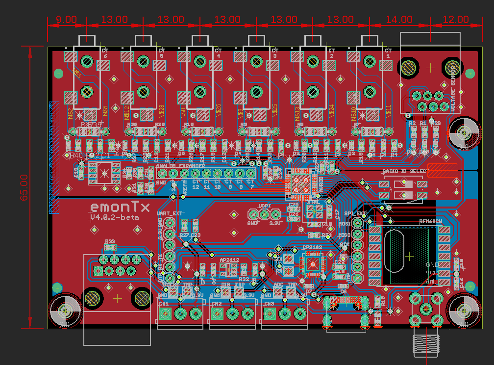
After testing the above board in the case we realised we can get a 6th CT on the base board with the potential to expand to 12 in total. So a bit more bonus capability! ![]()
A slightly amended board is being sent for the next set of prototypes:
@borpin this design includes the routing of 5V from the voltage sensing power supply through to the USB port, it looks like it might only be possible to power RaspberryPi Zero’s via the USB port used for data in this way due to back power protection on data ports on the other models, so we will likely need to include a USB-A socket on the voltage sensing board as well. Not quite as neat as I hoped but not a big problem.
The first EmonTx4 prototype has otherwise all worked perfectly: energy monitoring, ds18b20 temperature sensing, pulse counting, RFM69 radio, USB to serial converter, Im glad to report ![]()
That looks good - I am at a crossroads in my mains supply that after PV 7 years back (into main CU) then upgraded sub-main to garage direct from meter cupboard 5 years back for EVSE I really need to re-work my supply before I add battery and ASHP.
Trying to get a solid reliable electrician though is like looking for Elvis!
Tempted to try and get someone to put in a more indusrial board than domestic which has a lot more space to support CT clamps inside the CU for house circuits.
No bother. Is the UART exposed externally via the USB socket now? Can the internal UART header be used in the same manner as it is currently?
Yes
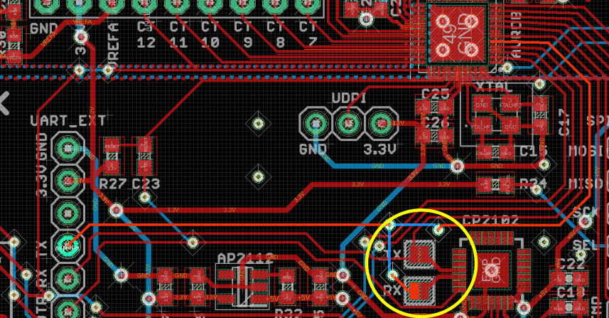
Yes and no, it is a standard UART connector so you can read from that connector without any issue, the RX line from the AVR is however connected to the USB to serial chip TX and so I don’t think you can write to serial whilst the serial chip is connected.
There are two solder jumpers that can be unsoldered to disconnect the USB to serial chip, allowing full use of that internal UART connector if required.
@borpin @Robert.Wall interested in your input on what RX/TX pin ordering we should have on the UART connector that’s on the EmonTx base board shown to the left in the picture above.
It is at the moment designed for easy connection to a standard USB to serial programmer. The pin labelled RX is connected to micro TX line and vice versa.
The issue with this is that it makes it hard to connect an ESP8266 based device such as an adafruit huzzah module directly to that pin out as you need to swap the RX and TX lines around. We have designed a custom module that does this but that then leaves the connector on that module with a pin order that makes it more fiddly to program the ESP8266.
Should the UART connector on base board have it’s RX and TX lines swapped around as we have it on the current internal connector on the EmonTx v3? It seems like the easy solution and that UART connector isn’t really needed for use with a usb to serial programmer as there is already an integrated programmer on the board…
I think, if it’s made clear that the user is expected to use the USB port for programming (because it’s a departure from established OEM practice), it’s reasonable to dedicate UART connector to the ESP8266.
The alternative (and I see no reason to do this - just saying…) is to duplicate the connectors - one with the pins arranged for an OEM standard programmer, and one for the ESP8266.
As long as the pins are labelled accurately, there shouldn’t be a problem. I daren’t even try to count the number of posts on here that say “the Tx pin is really the Rx pin, and vice versa” in response to the cry “My programmer won’t communicate with the emonTx”.
I can understand why they are solder jumpers, but a traditional one would be better (or a DIP switch). I can see questions - why doesn’t the internal UART work coming our way.
Can the 2 not be available at the same time?
BTW, is TX and RX the right way round this time? ![]()
Not sure this is progress ![]() I still feel the PiZeroW is the best wireless solution and it is a shame it is not better supported in the new version.
I still feel the PiZeroW is the best wireless solution and it is a shame it is not better supported in the new version.
If ESP is to be the supported method, then I suggest some effort is put into creating a component for ESPHome so the issues around setting up the ESP, keeping it up to date, flashing etc are easily resolved. I’d suggest that, in the long term, the support effort would be less.
Mmm - thinking about this - how would the ESP connect?
Seconded. I’ve been noticing the problems that people have been having with it in other areas here.
I’ve no experience with the PiZeroW, I’m just a little wary - for a reason I can’t put my finger on - of the ESP8266. It seems OK, but I’m just not comfortable with it. Certainly, if the PiZeroW runs the standard SD card image, or even something close, then it seems a no-brainer from the ongoing support aspect.
Thanks both, I think I will try and duplicate the connectors on the esp wifi board itself and keep the uart pin out on the emontx standard, it’s probably the least confusing option.
I will look into ESPHome and look a bit closer at the mounting options for the PiZeroW again.
Thanks again!
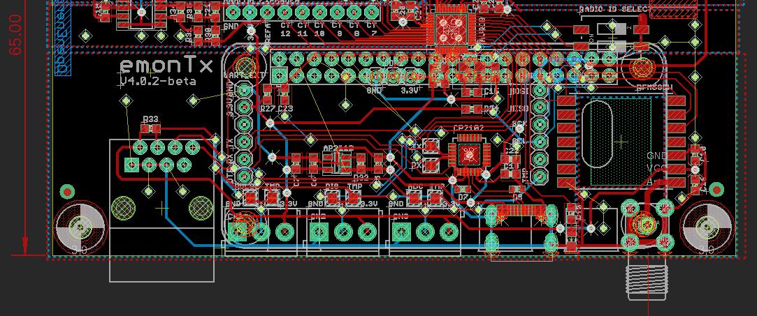
Overlaying the Pi zero footprint in a location that could potentially work, looks like this:
It would require only having a header that would cover the serial pins 2x5 rather than a full pi connector.
Question is, is there really utility in doing this vs just having the pi zero connected via the USB port and mounted externally? Which feels like quite a tidy solution in and of it’s self?
As Glyn has already mentioned it’s not something we can offer as an integrated product in the shop as the PI zero is really intended, as far we understand, a loss making educational product from RaspberryPi. So it would be up to individual customers to source and fit the Pi zero, including potentially soldering headers. Maybe it’s a configuration that would be worthwhile documenting in the guide at least?