From my perspective, providing the holes is a no/low cost to yourselves at this point. Yes, appreciate you can’t offer a complete solution, but having the ability to do it is, IMHO, a major boost.
Mounting inside would be ideal (although need to check the WiFi does work) - externally is just untidy - needs the ability to pass the cable out etc.
I would, at this point, leave the header/connection to the user - as you say, because the Zero does not come with a header as standard it can never be plug and play. However, if the UART can ‘just be used’ and has a header, there is little more an end user needs to do (header on Pi and a couple of wires/jumpers).
If you wanted to make it really easy, how about a JST connector on board as access to the UART and a 5 way cable? Just solder the cable to the PiZ and the user is away .
My disquiet is that there is no way to debug it. These modules are also a bit flaky when it comes to WiFi - I have had some that just do not like a particular router.
The other issue is how well the EmonESP software is kept up to date - security patches?
I’d be less concerned if this was just a component to ESPHome, as all the basic stuff is handled by that.
The only thing that needs changing is the RST pin allocation (IIRC) but that might just be for flashing the image to the EmonTX from PIO (yes I know…).
I guess for that to work, the PCB would need mounting holes that align with the PIZero? An advantage of say providing a 5x2 header is that it can simultaneously provide the mechanical fixing of the PIZero as well as the power and data.
Il try and do some testing of ESPHome, it looks like it has good ESP32 support, ESP32’s have better availability now from standard distributors as well.
Im going to stick with the option to mount the Pi Zero externally for now, but potentially revisit this again in a later version, time is a bit too tight on production for the first set of boards to put this in as an afterthought without good testing etc - plenty of things to prove out on this board as it is.
A brief update on progress.
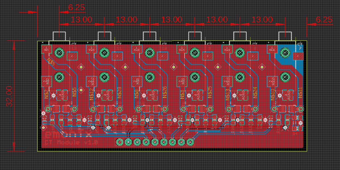
The updated EmonTx v4 design with 6 CT sensors and 5V power routing was sent for prototype PCB production yesterday alongside an updated 3 phase voltage sensing board (thanks to @glyn.hudson), a 6 CT extension board and a ESP32 based WiFi extension board. This should hopefully give us everything we need for EMC testing.
ESP32 Testing
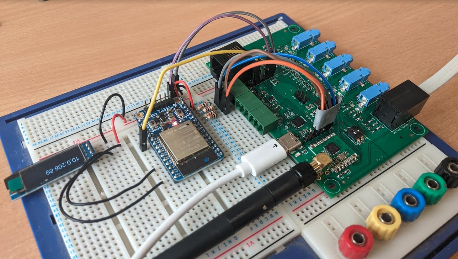
Using the ESP32 Arduino core and a ESP32 Huzzah I’ve been doing some basic testing of couple of things Im interested in making possible with custom ESP32 WiFi board that would attach to the EmonTx board including:
Moving away from sharing the same serial port for both programming of the ESP and receiving serial data from the EmonTx (making use of multiple hardware serial ports on the ESP32).
Interfacing with an 128x32 character OLED display in order to provide status information including connected IP address.
Taking over control of the RFM69CW radio from the AVR micro, so that the ESP32 can act as a base-station receiving radio packets from other radio nodes such as EmonTH’s whilst also removing the processing overhead that handling the radio requires on the AVR micro (allowing the code on the micro to focus on energy monitoring). This was the reason for the broken out SPI pins on the EmonTx v4 board.
There is, of course, a component in ESPHome for time - just saying - I’ll get my coat
You can also control displays too.
All I am suggesting is to use the reusable components around, that then allow the user to do what they want and reduce the burden of maintaining the code. Perhaps provide a port (SPI?) to plug in any display.
The priority is to get the baseboard with 6 CT’s in a single phase configuration launched first. I cant say for sure yet if we will have the extender available at the same time. There’s a fair bit of work on the firmware side required before it is ready, but will update here as we make progress on testing. We should have prototype boards back for the extender in a weeks time.
Not yet, I need to order that USB-C to USB micro cable and build up the next version of the v4 board with 5v routed to be able to test this. Will update once I have done so.
I’ve spent the last few years working with the ESP32 Arduino core, and my recommendation is to avoid it if possible - if you are writing code from scratch, use the native IDF libraries and VSCode.
The Arduino core lags behind the IDF framework, and also limits what you can do with the hardware. It also consumes a larger amount of RAM/Flash.
Thanks @stuart yes planning on doing that. I’ve got an interim prototype that’s just a basic ESP32 pcb with a header for an OLED as I didn’t quite get enough time to work through the best RTC to use and SD card socket for this batch of prototypes., but I’d like to add the SD card in the next revision once I’ve had a bit more time to do some more breadboard testing.
The ESP32 is reasonable at keeping it’s time running, even in light/deep sleep sessions. As long as it has a WiFi connection you can set it up for regular SNTP polling. IIRC the clock drift is 10sec over 24hrs.
Thanks @atanisoft I was thinking it might be nice to have the option to use it for offline logging to the SD card - in applications where doing a time sync via sntp might not be possible/reliable.
I’ve been looking at the MCP7940 which seems like a low cost RTC option, another might be the nxp8523. I’m also keen to not add components that the majority wont use so it may be an option to just have footprints on the board for these components that are not usually populated.
True, perhaps an option to have it only use WiFi once or twice a week to do time sync. In any case, an external RTC will still require an initial time sync and possibly periodic sync to account for drift.
But fully understandable to want to offer the offline mode with external RTC.