Am I able to pre order it?
Welcome, @Swwils to the OEM forum,
I’m afraid I can’t answer that. I think my best suggestion would be to email the shop, and if there is or will be a waiting list, then the shop will know about you.
Thanks for the reply.
It just seems with the current one out of stock and me having a solar pv + storage system here (3+ CT needed) that waiting for this is the best option.
Hello @Swwils Thanks for your interest. We are not doing pre-orders yet as the hardware is stil going through testing, but there will be the option to at least register interest and received a notification of when stock becomes available once production starts. The target for stock being available is still mid-late July.
Ok thanks!
At least this project doesn’t have a IMU in the BOM!
Wow! A 2200 km EV roadtrip followed by an extended Easter break, and I almost missed this thread completely. This looks great. I’ve been doing stm32 stuff for so long I’d stopped following AVR developments… good to see they’re still breathing new life into the old girl yet.
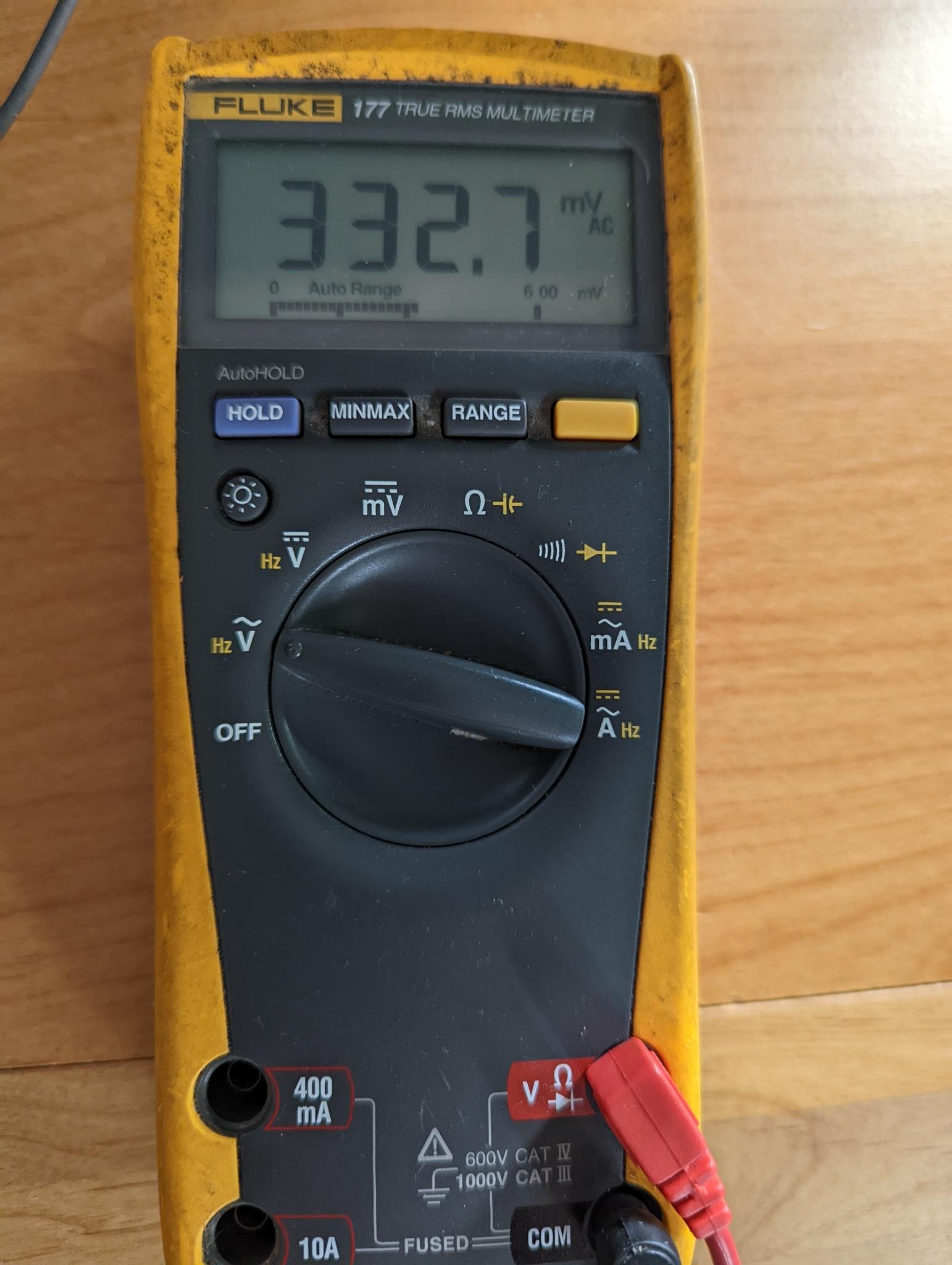
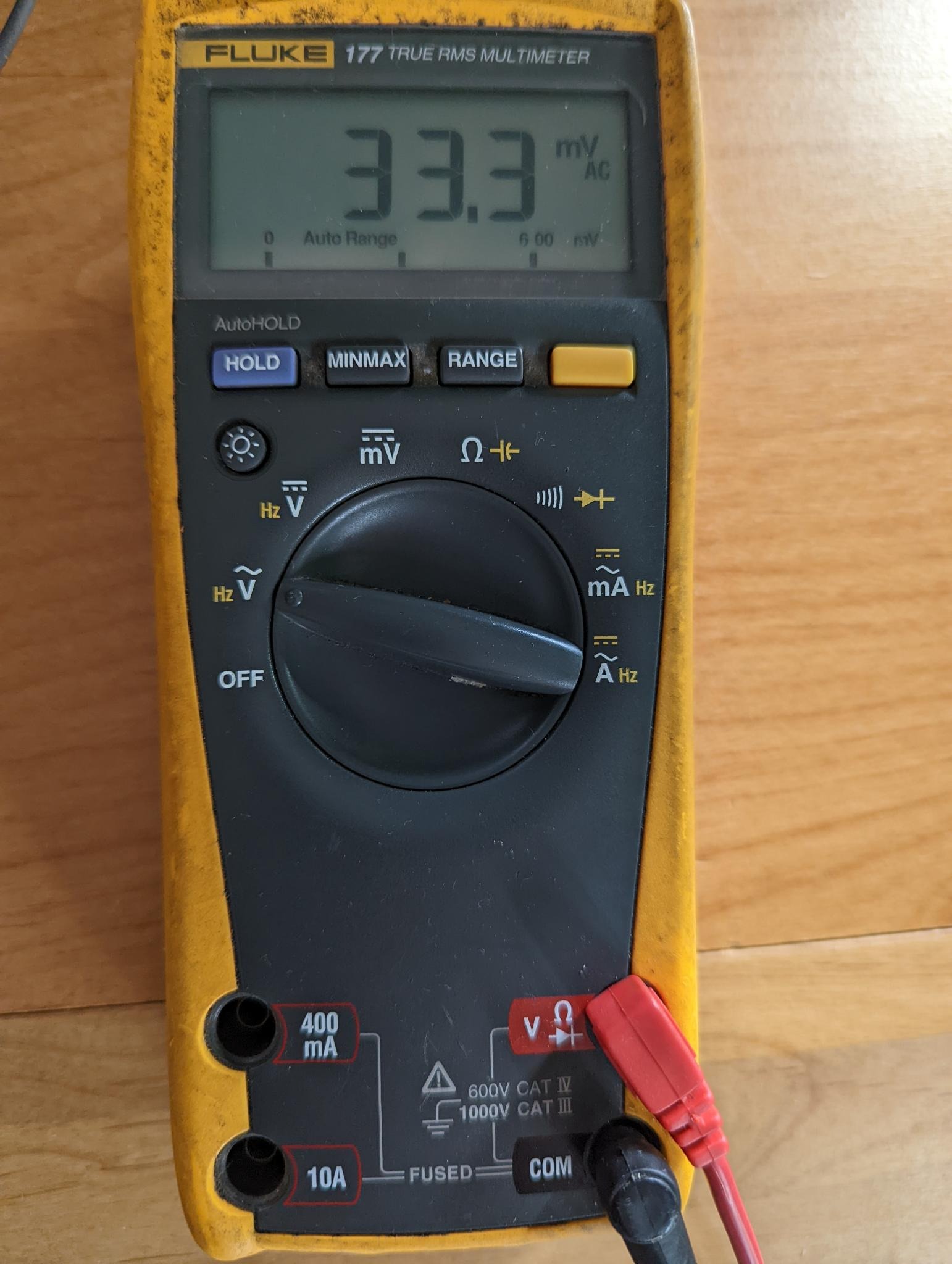
I think the move to 333mV CTs is a good call. It moves a significant part of the calibration problem to someone else - and generally they seem to do a pretty good job of trimming their CTs. The CTs also seem better behaved when they’re not trying to generate big voltages across large burdens. The only downside is you end up having to measure pretty small voltages down the low end of the scale, so noise can be an enemy. What reference voltage do you envisage using, or is that still work in progress?
Good to see a proper 3 x V approach to measuring 3 phase power too. I’ve always had my doubts about measuring one phase and extrapolating the rest. No doubt there are plenty of places where that approach gives adequate results, but the problem is you’ve no way of knowing if you’re in such a place. I’ve never been assured by the standard response - compare it with your revenue meter over a month and report back. Just about anything can look good using that yardstick - even not measuring V at all. If you want to know how much power a device is using right now, there’s no option but to measure the V it’s connected to.
Do you know how much current your voltage sensing board draws on the primary side? My calibrator is only good for 20mA on its voltage output and it’s not great with very reactive loads. It’s a good match for meters that use R dividers to measure V, but has always struggled to drive the standard AC wall-warts used in previous OEM designs. From memory it starts to distort at anything much above about 220V when driving the standard Jaycar wall-wart that most OEM users use in Aus. So if you have any design choices there, keeping that primary current low might be useful if you ever want to hook it up to a calibrator.
Hello @dBC good to hear from you and thanks!
Nice! where did you go?
We are planning to use the internal 1.024V reference voltage - calibrated using an analog reading from a precision voltage reference. Unfortunately the external analog reference supported by the chip cannot be lower than 1.8V, we’d be throwing away quite a bit of resolution if we used 1.8V directly with the 333mV sensors.
The first iterations of this design are intended to keep things simple as we have a relatively tight turn around on this. The intention is to evolve this design in future to include things like a buffered bias and potentially the op-amp based input conditioning circuit developed by @Robert.Wall and @danbates in the STM32 design, that would both allow direct use of an external analog reference and reduce phase errors a bit further on the ZMPT101’s.
Without the AC-DC power supply module, the current consumption of each ZMPT101 is in the 1-2mA range.
Great!
From Qld to Sydney and beyond to Royal National Park and the Illawarra. It was my first chance to do a proper roadtrip in the EV since the state borders opened up post COVID. With 350kW ultra-rapid chargers every 200km along the A1, charging was never an issue.
From memory those internal band gap references are very stable but not particularly accurate, so your solution sounds perfect. Do you just self-calibrate each time you boot?
That would be well suited to hooking up to a calibrator should you ever wish to do a spot-check on your accuracy.
If possible, it might be worth keeping the AC-DC supply sourced from its own terminal that you can just loop to one of the Line inputs at installation time. Have a look at the photo here and the description here, to see what I mean.
An earlier version of that meter had the power supply internally hardwired to L1 and that caused grief when trying to put L1 on the calibrator as the calibrator’s voltage signal (20 mA limited) got distorted when the SMPS did its thing. Breaking them out like that makes installation ever so slightly more complex (one more loop) but means in the lab you can power the SMPS directly from the mains and point the calibrator at the ZMPT101.
Sounds like a great trip! Envious of your 350kW charging, still on max 50kW on my leaf!
Credit to @Robert.Wall for this solution, when it’s sampled to be determined.
Interesting, perhaps a jumper link of some kind? that could be removed and connected seperatly during calibration… ?
Actually, the chargers can do 350 (reportedly) but my car can only do 110, but I regularly saw it sucking 109 kW so things were pretty quick.
Yeh, that’d work. Your design is such that it probably won’t need per-device calibration (other than the stuff it does internally via the reference voltage). So you probably don’t want to pollute it too much to make it calibrator-ready, but if it’s easily achievable it would allow spot-checks to see just how accurate it is. Send one to me and I’ll happily hook it up ![]() - but only if I can drive the V inputs separately from the power supply. I learnt that the hard way with the earlier version of that meter referenced above.
- but only if I can drive the V inputs separately from the power supply. I learnt that the hard way with the earlier version of that meter referenced above.
Actually, we’d need some sort of link on both Line and Neutral, like in the pic referenced above. I can’t connect the calibrator output to anything that’s connected to the grid. So the grid would drive the Line/Neutral pair running to the power supply, and calibrator would drive the Line/Neutral for L1, L2, L3.
Perhaps rather than complicate the design it might be easier to provide a voltage sensing unit without the power supply and then a separate unit with just the power supply for calibration purposes?
Will the voltage sensing input be rated to 440 V (=415 +6% or 230 × √3 + 10%) ?
I can foresee somebody wanting to measure Line-Line voltages while running the power from line-neutral. I can’t quite see why they’d need to do that, if the voltage processing is sufficiently versatile, but I can see the question being asked.
And of course for the Norwegians with 3-wire 230 V, all 3 voltage monitors will need to be connected in delta. (Though in this case, connecting the voltage monitors in star should give accurate whole-house line currents and per-line powers, I’m not sure what that would mean and how useful it would be in practice.)
I like it. Effective and simple.
I thought a major (selling) point was a combined monitor/power ‘box’ - at least for single phase users - that had one mains plug, not the two that the present emonPi needs. Unless you go to a mechanically complicated piggy-back arrangement, doesn’t this mean internal links much like @dBC 's meter?
I had something like that in mind as soon as the concept was mentioned. It could be sold pre-wired for single phase with a UK, EU or AU plug and lead, or with no lead for hard-wiring into any - single phase, split-phase or 3-phase - installation.
I don’t like the idea of two hanging-off boxes, potentially with two leads and two plugs requiring two mains sockets.
Agreed, but I think that was only intended for lab work - i.e. allowing me to drive the V inputs from the calibrator, while letting something else power the box. Everyone else would use the single external box that drives both the power supply and the V inputs.
In the latest iteration of my meter, we’ve gone for 3 external (L,N) pairs, one for each phase. There’d be a 4th pair for the power supply, but we moved to PoE for that. So it’s effectively 3 single phase meters, completely isolated from each other. The end user can then decide whether to tie their Neutrals together via loops at the screw terminals.
OK, but then there are the 3 variations that I alluded to above:
- Single phase plugged.
- US split phase wired.
- UK/EU 3-phase wired, or maybe plugged.
I don’t know if a L-N-L + PE US plug exists, @Bill.Thomson will no doubt tell us.
When I lived in the US, I’m pretty sure my dryer plug was a 4-pin arrangement.
They do, but the L-N-L sans PE connector, is used here as well.
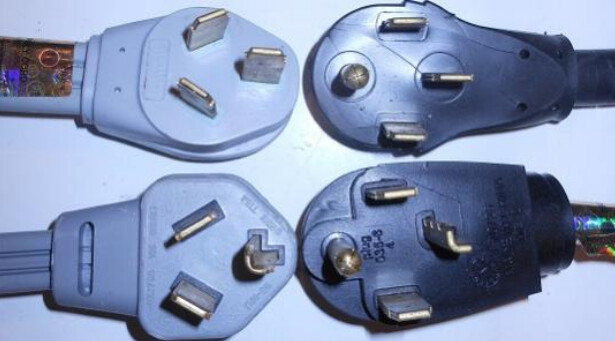
Typical use for these are clothers dryers and stoves/ovens.
Other examples: mains powered arc welder, recreational vehicle (caravan), pottery kiln.
In general, 240 Volt loads that require a 30 or 50 Amp circuit.
They’re not usually found in an environment where natural gas is used for cooking and
space/water heating. (No electric stove/oven, space/wather heater or laundry dryer, so no 240 V circuit)