Hello,
Well that was easy and I will now have another go!
First the context.
The property was built in 2010 and the insulation level is to modern standard. It has a system boiler supplying a simple ring main that supplies 7 separate circuits, a HW and a small rad circuit and 5 separate U/F heating manifolds located at various remote locations, which control 18 separate circuits. The Polypipe heating manifolds work well, but the control system was never that good when it was installed and so the control system has now been undated. The simple controller has been replaced with 7 Optimum wi-fi controllers, which work well and enable separate control of the H/W & Rad circuits and the 5 U/F heating manifolds with separate temperature control of each of the 18 U/F zones. The property also has 8.5kW of solar fitted, an original 4kW fitted in 2015 and an additional 4.5kW with dc batteries last summer. I also have a Solar iBoost fitted which did work well, but is incompatible with the dc battery system so will be changed to a Powerflow unit before the spring. So very broadly I am now reasonably confident the solar together with batteries to time shift demand, will meet the majority of the property’s hot water and heat demand from April to September. The property is also fitted with a number of air-con units and since October 2 of the units have been very successfully operating for 22 hours a day which has significantly reduced the gas demand.
The property was designed in 2009 and heat calculations were prepared and I have now had 12 years of experience and the heating system is certainly over sized. I have now purchased a 16kW Samsung ASHP (AE160RXYDEG), but even with the air con units that are fitted I have decided to split the heating system and keep the existing gas boiler to feed the H/W and small rad circuit at 60 degrees and use the ASHP to feed the 5 U/F heating zones at 35 degrees. This should be straightforward, but after a considerable review of the ASHP market, it appears there is no clear settled view on what is the ideal or optimum approach.
So the question that I would appreciate any advice or comments is there appears to be three general approaches that various suppliers and installers suggest:-
A 4 port buffer tank to create a hydraulic separation between the ASHP and the heat circuit, whilst this is not a true separation, it deals with the volumetric issue due to potential loss of system capacity when demand reduces and 2 port valves close. In addition it also creates a heat sink that is used during the de-frost cycle. I am reasonably convinced that this approach is probably the best option and I have already purchased a 100 litre buffer vessel.
There is also an opinion that whilst it agrees that a buffer vessel is necessary, the turbalence that is created in the buffer vessel by mixing causes a temperature step change and this will have an impact on the thermal efficiency of the process and lower the overall COP. This view is supported by a paper on the subject from Ulster University.
The third view is a buffer vessel is not needed as modern ASHP’s can modulate the output to better match the heat demand.
Also and whilst I don’t want to fit at the moment, it is obvious that continuously monitoring the flow temperature in and out of the buffer vessel would be useful and tracking this information and comparing with COP data. Having looked at the various impressive data on the forum, this is certainly something I will look at once the new Samsung unit is operating.
So in conclusion before I complete the installation any experience, advice and in particular anything associated with a recent installation of latest Gen 6 Samsung unit would be much appreciated.
And also a thank you to Glyn Hudson, your YouTube tutorial was very useful, I was already aware of the issues associated with glycol and was aware of antifreeze valves, but your experience helped me to make the decision to fit antifreeze valves.
RJK
I have a Stiebel Eltron WPL 25AS heatpump and associated HSBC200 hot water and buffer tank system. It’s all integrated together, and whilst I’m not an ASHP expert, it’s use of the buffer tank (which is 100 litres) does seem to make the system pretty robust and smooths out temperature shifts as the heatpump kicks in and out.
The Stiebel system has ethernet modbus available, so I can examine this for things like flow rate, flow and return temperature etc, as well as hundreds of other parameters and readings. It enables me to calculate CoP on-the-fly, as well as gather cumulative data, and I find that the instantaneous calculation of CoP using this information is both enlightening and reasonably accurate (at least in terms of variation, if not absolute values).
I’d be happy to share more data on how my system performs if you’re interested.
Thank you for making contact and the offer to share data on your system.
The main question at this point is how a buffer tank affects the performance of the system and in particular the CoP.
So could you please advise how your operational CoP compares with Steibel Eltron’s quoted figures?
There is huge amount of information available on the web about heat pump system design and a lot of examples of poor design where people are only achieving a CoP of 2 – 2.5.
Thank you again for the contact, I look forward to your response and my current aim is to install my ASHP in the next couple of weeks.
Monitoring the power consumption of the heatpump and using the flow/return temperatures and flow rate (from the heatpump’s own sensors), I calculated that the CoP overall is around 3.83 – this is for heating and for hot water combined.
The hot water is only on for a 10-20 minutes a day as it heats up very quickly. During these periods, flow temperature from the heatpump reaches 64 deg C (flow meaning from the heatpump to the buffer tank or hot water tank). The target temperature for the hot water is 53 C.
The heating turns on and off during the day, controlled by the room stats, and when it’s on, the heatpump flow temp reaches a maximum of 43 C and averages about 38 C. The return temperature (which is effectively the buffer tank temperature) is typically 5 C below the flow temp. This is then the temp of the heating water which flows around the radiators and the underfloor heating (although that has its own manifold mixing system which is normal for UFH).
The heatpump also keeps a running record of how much heat it produces, and its own power consumption, and it splits these between heating and hot water. Its figures give a average CoP of 4.09 for heating, and 2.29 for hot water. This was measuring yesterday, when the ambient temperature was ranging between 5 and 8 C.
Stiebel’s own quoted figures for CoP in their design package (here: Wärmepumpe ) seem to match this pretty well.
Thank you for the data and it is really appreciated.
My concern was the buffer vessel would have a significant negative impact on the overall CoP, so it is good to see that your performance figures are a reasonable match to the manufacturers design figures.
As stated in my previous email, I am only using the heat pump for the UFH zones. The house was built in 09 and the heating system has worked well, but I now realise it was never set up correctly and probably with cheap gas and an input temperature of 60 degrees it probably didn’t matter. I intend installing the ASHP in about a week, so I have now started resetting the existing UFH manifolds to the correct flow input temperature and flow rate.
At the moment I don’t know what information will be available from the Samsung control system, but if it doesn’t enable the COP to be tracked I will install the necessary sensors later in the Spring.
So thanks again and for interest I will send you a summary sometime in February of my first impressions.
From what I read here, I think it is a good idea to install a heat meter and an electric meter that you can access to get the data locally. Install ‘pockets’ for temperature sensors and a flow meter again so you can get this data locally. Relying on the manufacturers systems seems prone to issues, and being able to properly measure and record what is going on is vital to getting high COP. The investment will be repaid.
Thank you for your comments and I was intending to fit later when I can see how the unit is operating.
But I will take your advice and fit now as the pipework is installed.
It will make sense to use the type of instrumentation that is commonly used on the forum, so can you please give me an idea what are the instruments that others find most useful, also the communication protocol and software that is used?
Always cheaper in the end, and as soon as it is running you will want the data
Choose with care and look and see what others have been able to access the data from. Not all meters are easily accessible. OEM do a package in the shop. Email them for advice. I don’t have a HeatPump but read everything
Hi Andrew,
I also have a Stiebel Eltron heat pump system like yours. It has a Service Gateway device to access some of the data through Stiebel’s software/apps. How are you managing to get the data out to use youself? And into OEM? Please can you show us how to interface to it?
Thanks,
Matt
The Stiebel Eltron system has a Modbus interface which gives access to hundreds of Modbus registers. It’s all documented here:
It takes a while to understand all the registers and how their data are formatted and presented…
You can access the registers over the Ethernet connection to the Service Gateway. Modbus typically uses port 502. If you have an iPhone can have a quick look by using Modcomm Peek and Poke:
It’s a useful little tool for examining Modbus registers. There’s probably something similar for Android phones, and there are also several Windows and Mac based utilities for reading and writing Modbus over Ethernet or RS485.
Having established the correct access route, I wrote a VB.Net application using visual Studio 2017 to access the relevant registers periodically – I use 10 second interval, but that’s probably more than needed for general purpose work. I then analyse all the data coming back, and log it into CSV files for further inspection. I also created a GUI to show the data graphically, and have integrated into it various power consumption sensors using an EmonTX from [Open Energy Monitor] (https://openenergymonitor.org/ ) which give me access to grid power, heat pump consumption and so on. Their stuff is brilliant, works well and isn’t ridiculously expensive.
My VB.Net application uses a paid-for Modbus library which makes it very straightforward to read and write registers: there are various suitable software libraries out there. Note that I don’t write anything to the heat pump (yet) – I’m just monitoring it.
I had a few old OWL power sensors which send data via a 433MHz link to a Raspberry Pi system running Domoticz: this then forwards these readings on to my application using MQTT, which means I can monitor more power levels without spending any more money . I’m using various NuGet libraries in Visual Studio, including MQTT, to make it easier. I’ve got another spare Raspberry Pi providing an MQTT server facility.
I also “scrape” the ServiceWelt webpages of the heatpump Service Gateway, and extract some further information from those which isn’t contained in the array of Modbus registers, like daily and lifetime heat output and power consumption: I can then compare these with my own calculations of heatflow (using flow and return temperatures and flow rate) to work out CoP.
Hope this helps – it’s just a brief overview and I’ve spent quite a lot of time working out how to do it and refining the programming.
Thank you very much Andrew for your detailed reply.
Extremely interesting and exciting. For me at least!
I have put a Modbus TCP app on my phone and can indeed send and receive information to/from my heat pump internet service gateway. I have also read the manual with the link you gave, all makes sense and I can see all the fields I want to data log. I have also researched how to make an Interfacer in OEM to connect to the TCP Modbus and log the data in OEM.
Next I just have to put it all together and get it working. Assuming I manage this I will post my Interfacer code here for others to use OEM with their Stiebel Eltron heat pump ISG.
Brian, I did not know HomeAssistant existed, this also looks very interesting, but for now I can only manage one project so I’ll stick with OEM for the moment.
Sorry Brian, bad wording by me. When I said ‘make’ an Interfacer I really meant make the config file adjustments to use the existing Interfacer like others have done. In progress right now, but not going great, log file says:
ModbusTCP  Not connected, retrying connect {'modbus_IP': '192.168.1.199', 'modbus_port': '502'}
ModbusTCP  Opening modbusTCP connection: 502 @ 192.168.1.199
ModbusTCP  expected bytes number after encoding: 4
ModbusTCP  datacode h
ModbusTCP  reading register #: 507, qty #: 1, unit #: 1
ERROR    ModbusTCP  Connection failed on read of register: 507
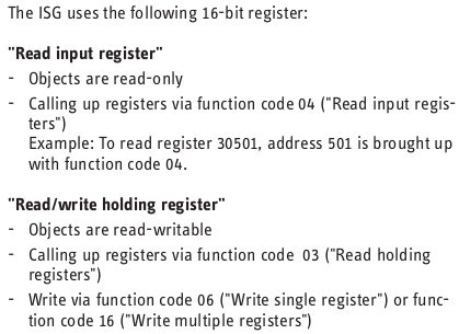
I’ve worked it out, I can read some registers but not others because I don’t know how to make the Modbus TCP Interfacer switch read mode. ISG instructions say:
I can read the holding registers so Interfacer must be using function code 03 by default. So how do I tell it to switch to Modbus function code 04 to read the registers I’m missing?
I’ve read the python class and though it is a bit beyond me, I can kind of see what it’s doing.
I guess the quick and dirty way forward would be to copy the code, rename the class and switch the read function, then when defining the interfacer you could pick which version to use with different registers.
A much better and nicer way would be to upgrade the class to include a way to define which read function you want to use as part of the definition of registers to read…
Either way, how would I include a code change (any code change!) inside my running Pi? Would I have to manually compile everything and make my own image to run?
How often is OEM released with improvements included?