This is not a great fit for a temperature sensor, so the heat calculation could be off. The other sensor is likely done in a similar way on the other primary pipe. I would suggest redoing them with some combination of thermal paste and/or copper wire. See some fixing methods on this blog here: Temperature sensing with OpenEnergyMonitor – John Cantor Heat Pumps
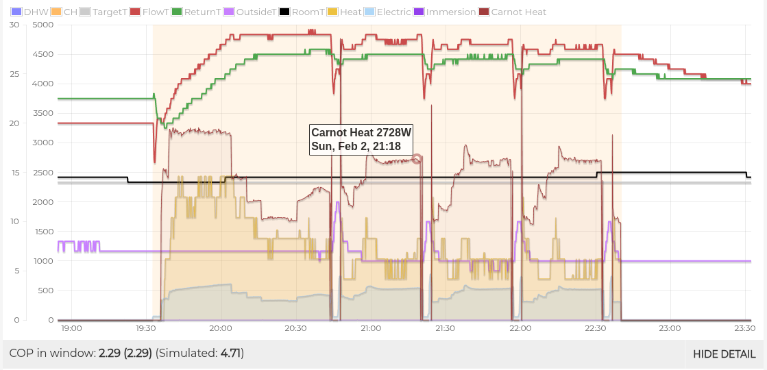
Heating 200L of water from 35° to 53° requires 4.2 kWh of energy, yet this heating period only produced 2.6 kWh. This says to me that the heating power is being under reported, due to poor attachment temperature sensors (a common problem). Actual COP might have been closer to 3.3.
This period shows the flow and return temperatures falling together while the pump is on, which is a good sign, or shows that both sensors are equally bad.
Defrosting every hour is about normal; quiet mode might help with that.
…though this period and this period shows the flow temperature slightly below return, which ought not be possible.
I also see that your system runs the pumps whenever the outside temperature drops below 4° - this is Ecodan’s “anti-freeze” mode. Does this mean there’s no glycol in your system?
I can’t find the other sensor which is weird, can’t see another grey wire. I’ll look at how to connect that better.
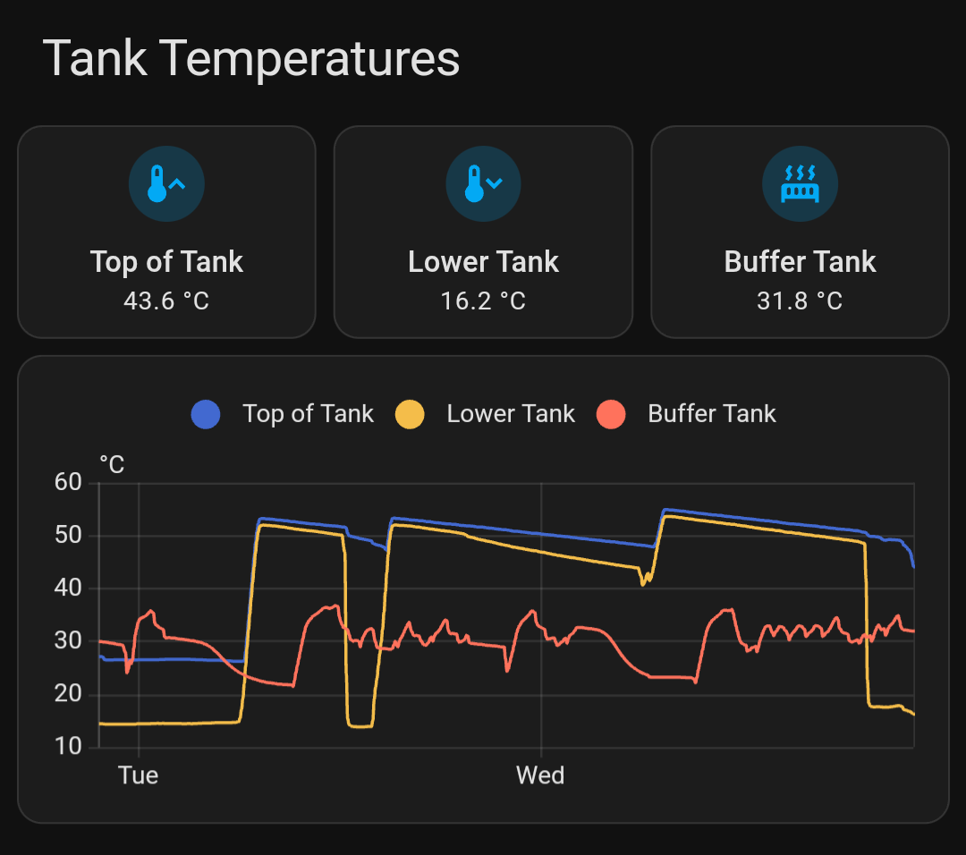
For the water I do have the sensor at the bottom of the tank so the top was still warm. I have it at the bottom to make sure I have plenty of hot water.
For example this is my setup right now and the ASHP sensor is at the bottom.
Getting those sensors fitted better will likely make a big difference.
The heat pump will run the primary pump (grundfos?) at a fixed speed (5 in settings), and the flow rate (10 l/min) will be the result of that setting. Reducing the speed will increase the dT between flow and return. This doesn’t influence COP much, but will mean slightly less power going to the pump. Errors in the heat calculation might also be smaller as a result.
The second pump (wilco?) will be circulating the hot water out of the buffer to the radiators. The optimal configuration would be to match the flow rate of the radiator circuit to the that of the primary circuit. This is a bit of a faff to do, and needs either a second flow meter, or measuring the temperature at the 4 ports of the buffer. Some details in this topic, though probably not worth putting much effort.
I think the pumps are the other way around given the flow rate of the heat pump seems to align with changing the wilco.
I’ve lowered them both slightly to see if it helps. I can tweak them over the next few days to see if it helps. The grundfos only has 3 settings by the sound of it it was in the middle so I’ve lowered it to the first. Will see how it does.
Thanks for your help, will feed back. Temp sensor updates should be done Friday.
Note changing the 5 in settings has no effect I think this is because the PWM of the pump isn’t hooked up and is instead controlled separately / manually.
Oh, and another thing - plotting the idealised Carnot heat output at 50% shows how much heat you would expect to get given the flow temperature vs. outdoor temperature. At this power level and flow rate, dT ought to be closer to 4° with COP around 4.7.
Carnot is a formula that simulates how much power a heat pump will output, and all (well metered) installations will fit between 40 and 60%. Yours it falling well below that, reinforcing my suspicions that the system is under reporting heating power, and is actually performing much better.
Have installed it, will see if it makes any changes. Yesterday was better with lower flow rate but also it was on a lower setting as I was out most of the day so not a true reflection.
Put some paste on the pipe and probe, made contact with them. Wrapped with a thin copper sheet. Taped + zip tied the sheet (so it didn’t unroll and to make tight contact with the pipe). Then foil around that and then finally the normal lagging stuff.
Not seeing massive immediate changes but will give it time.
I’m going to install some of my own ds18b20 sensors into an esphome device. The ecodan is only 0.5 accuracy and like you say sometimes ends up with delta t being negative during anti freeze.
Unfortunately not much difference after installing my own sensors. Does change a bit but not a lot. Wondering if there is something funky with my system. Delta T just doesn’t seem to maintain itself very high.
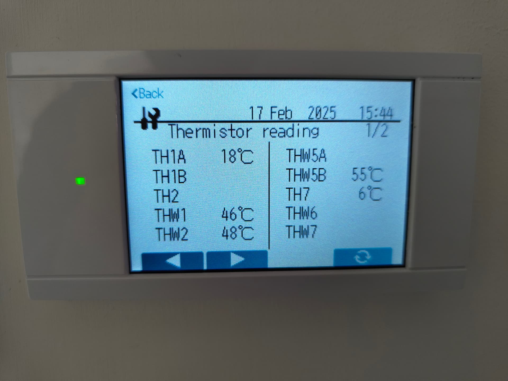
generally, the temperature measurements look good, though flow is 0.3° higher than return. You could apply a calibration offset at an appropriate point in the data processing.
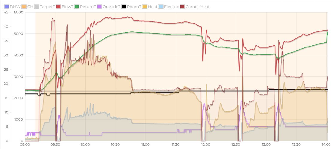
9:00 sees end of nighttime setback, triggering the start of the heating. Heating power increases, though is below expected output.
at 9:30 the heatpump does a defrost because it’s noticed the lack of heat
heatpump delivers nearly 4kW of heat for the next hour, before modulating down to lower power. Heating power matches to Carnot formula reasonably well (red line, factor of 0.43).
from 10:45, heatpump settles into a nice steady state, delivering an even 2200W of heat for 800 W for one hour.
around 11:50 we see the heating power falling away despite the same input power, which indicates that the outdoor unit is frosted up.
Overall COP up to this point is 2.9, which is close to what we would expect for these conditions.
after the defrost at 12:00, the heating power doesn’t recover as one would expect, not even managing the output it managed before the defrost. Flow temperatures are dropping.
at 12:30 it tries another defrost, but is again unsuccessful
it tries a 3rd defrost at 13:10, puts in a bit more effort, and by 13:40 has managed to operate properly again.
14:00 sees the start of the water cycle, which I’ll comment on separately
I’ve spotted this pattern happening a number of times on your system often around midnight. You might want to go look at the outdoor unit and check it’s defrosting successfully.
TH3 is the liquid pipe 1
TH5 is two phase liquid pipe
Its the thermistors fitted at the back of the outside unit (th3 bottom, th6 top). For me if delta temp between th3 and outside >= 10k, its going to defrost