Further investigations with Optical Pulse Sensor connected to emonTH. No external pull-up or pull down resistor connected for these measurements, but a 0.1 uF capacitor left connected between IRQ and Gnd.
Vcc = 3.346 V
Virq with sensor in darkness = 0.745 V
Virq with sensor illuminated = 3.333 V BUT the LED on the sensor can be misleading ie in partial illumination Virq varies with light level but the sensor LED remains off. In partial illumination Virq can be as high as 3.330 V (ie high) and the LED still off. I expect this is one reason I was getting spurious counts – as I moved the sensor the LED said it was in darkness but was still getting enough light to be seen as a high.
Pulse count only increments on a positive edge of the IRQ. IRQ is normally low when the sensor is plugged in, and goes high when there is light on the sensor. This initially threw me, since if the sensor is unplugged the internal pull-up raises Virq to 3.336 V.
Using a 1 k ohm resistor connected from IRQ to ground, with the sensor illuminated, 2.58 mA of current was drawn. Voc = 3.333 V therefore the internal source resistance = 292 ohm.
Using a milliameter connected from IRQ to ground, with the sensor in darkness, 0.08 mA of current was drawn. Voc = 0.745 V therefore the internal source resistance = 9.3 k ohm (ignoring meter internal impedance). Similar source impedance is seen if testing from IRQ to Vcc.
Looking at the numbers above, an additional external pull-up or pull-down resistor is not needed for noise elimination, but I still think will influence sensitivity – hard to go further without a circuit diagram. I’ll still keep the 0.1 uF cap to try and filter any spurious noise.
Have run with the 0.1 uF cap for a few days, and pulse counts align with meter readings. Have only used a few kWh so need to let it run for a bit longer.
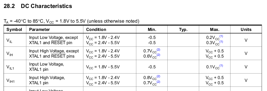
I’m interested how the sensor works at all since the Arduino HIGH trigger voltage is about 0.6V.
EDIT. Correction from further on in thread: High trigger is 0.6Vcc, for 3.33V supply that’s 1.98V.
Would you be up for a couple more tests I could suggest? I don’t have a sensor where I am these days.
I’d add - for the benefit of anyone less experienced in these matters who is reading this, that those ‘resistances’ you’ve calculated are probably non-linear, and probably vary quite a lot from device to device. You also found that between the ‘on’ and the ‘off’ states, there is a more or less linear region where the output is proportional to the light intensity. So there are not two distinct output states as the manufacturer’s description seems to imply, but rather a ‘low’ state that corresponds to very low light levels, a ‘transition’ state where the output is some function of the light level, and a ‘high’ state where the sensor is saturated.
My take-away point from all of this is, if the sensor can see any ambient light at all, ignore the LED on the back and check the output voltage for correct operation.
Thanks everyone for their assistance. As an aside, I have run the same type of sensor connected to an emonTx for 4 weeks on two different commercial premises (several thousand kWh - a friend who was concerned about his high bill and wanted to look at different tariffs) and the pulse count lines up exactly with the revenue meter register. The switchroom in question was a locked room, lights normally off hence pretty dark. Once again comes back to the comments on installation care and ambient light shielding
For a future design note which I hope will be taken into account because the light leakage issue is recurring.
Bearing in mind the testing did not check the effect of pull-down/up at low/high light levels (and thus I make an assumption on the varying impedance) that in a signalling application such as this it’s fairly obvious a pull down and cap are necessary. The cable is one meter long, installed along side potentially high amperage cables, and clearly the device doesn’t have the function of sinking much current at low light levels.
I would like to be proven wrong if possible, as I keep learning.