Hi,
Thanks all of you for this great open hardware-source Project.
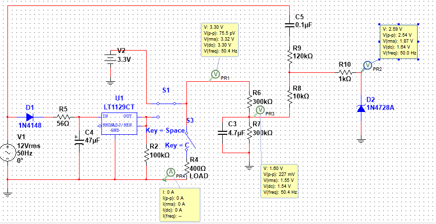
I have made a little project to see my modified sine wave invertir’s wave form.
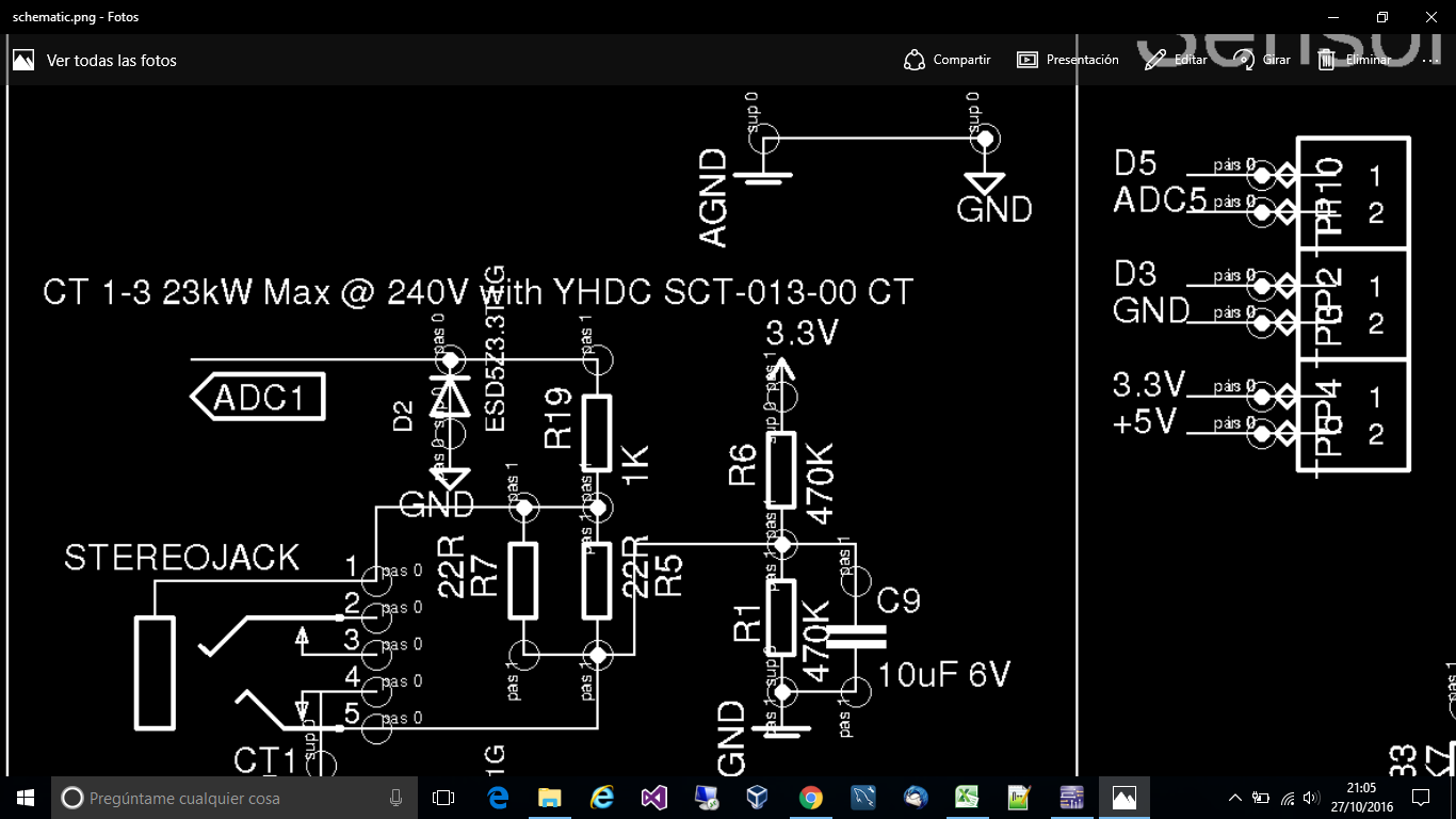
I have solder all components as emonTx’s schema (only one ammeter input). But I have found a strange error in my hardware.
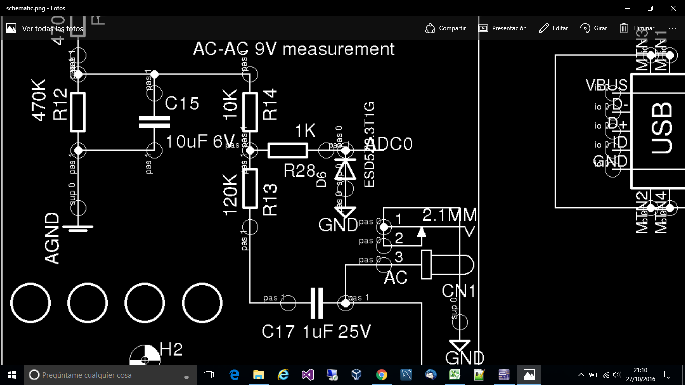
The schema shows a 1K resistor and a 3.3V zener diode for the input of each analog value.
I have been getting crazy because, with any load, I could only get 1.43 Vdc in that pin, instead 1.66Vdc (more less)
I have found, after doing a lot of change in components and getting crazy, that if I disconnect ZENER diodes, I get 1.66Vdc and get it working.
With ZENER diodes connected, I get 1.43Vdc and the wave of an AC-AC adapter goes above 0Vdc. Without them, I can see perfect my AC-AC wave.
The way I have solder the zener diodes is::
-
zener’s side with the line mark to the “end” of 1K resistor. That point is also connected with the analog input of my arduino uno board.
-
zener’s other side to ground.
1K---------////----------------> to analog input
|/
/ /
/
/
/______
|
|
__
_
I have already changed one of them. Same result. I bought them one year ago to china (ebay).
May be they are defecctive ? The circuit is ok, as without zener, I can get a perfect sin wave between 100 and 900 (range for arduino 0-1023) analog values. I have powered it with 3.3V (it is a arduino buono, with both 3.3V or 5V power options; grounds connected, power rail from arduino 3.3V; (I have also tried power the emonTx hardware directly with AC-AC adaptor, same result: with zeners, bad, without them, perfect), …
I know I could change them with a BAT54S or similar. But for me, a newbie, the zener diode is very simple, but I don’t know what I am doing wrong.
Regards,