Following up on Particle emon shield

While trying to see about making my own Particle Photon Shield, I stumbled upon this old thread incorporating the buffered bias voltage from user bruce_miranda. Unfortunately, the archived posts don’t include pictures of his pcb/schematics, and the Wayback Machine doesn’t have them either.
https://openenergymonitor.org/forum-archive/node/11292.html

Anyone have any updates on this or the shield that Roeland54 made here?
https://easyeda.com/roeland54/Photon_emon_shield-lFDBzUSs2
My plan is if either of those boards have seen some use and worked well, I might order a couple and save myself from duplicating any work.

You could try looking in

(But don’t hold out too much hope - the file names mean very little, I’ve found you need to open every almost file and look at the contents.)

Sadly, losing all the diagrams attached to posts was a serious failing of the archiving process.

Yeah, it appears to truncate the 2500 files down to about 1000 files. The wayback machine shows the file name of the jpeg, so that’s helpful, but no dice on finding those files. Thank you for the link though, there is some neat stuff that survived. I see that bruce_miranda, the creator of the original post is here as well, but it appears I’m too new a member to be able to message people.

Hopefully no longer - I’ve upgraded you by a notch.

That does hamper searching for a file online, but if you clone the repo (or download the zip) you get the full compliment of files.

It’s only whilst viewing via the GitHub site they truncate the list, if/once you know the file name you can access the file directly, they just truncate the list.

That will have to be done on my personal, as this work computer and hotspot are not conducive to downloading large files. Thank you!

Question about Roeland54’s board, linked here.

Or for ease of viewing, I uploaded it here.

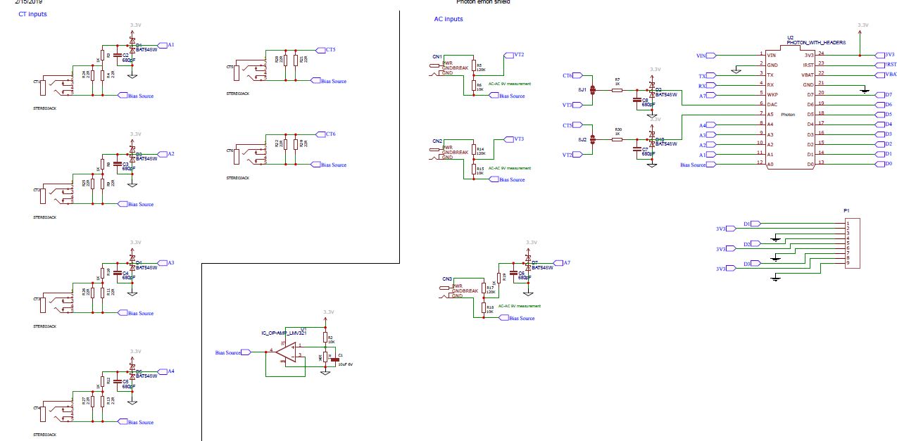
I was wondering what purpose the diodes, BAT54SW, are for. I’m guessing for transient voltage suppression, and according to an older post from 2016, you remarked that this isn’t necessary, but I just wished to be sure for this particular design?

That does indeed appear to be the obvious reason.

Looking back at that old thread, it appears that no diode was a better choice than the leaky one. The designer of the circuit needs to weigh the probability of a damaging spike reaching the inbuilt protection diodes of the ADC input. And that could depend largely of the fault current that the c.t. is likely to see and how the c.t. responds to that fault. It will be best to have a diode that functions as intended, rather than none; and none might well be better than one that causes the circuit to not operate as intended.