I’m new to this forum, and have been working on an Arduino mega2560 based power monitor that uploads to emonCMS. My prototype supports 15 channels on the mega, datalogs the power to a local SD card every 10 seconds or whatever, and uploads to emonCMS.
I’ve taken some fresh approaches to a few of the problems that I see discussed here in the forum, and I’m wondering if anybody else is doing any of this:
One of the first things I did was take all the floating point arithmetic out of the sampling loop. That increased the sample rate considerably. Then I doubled the speed of the Arduino ADC - by setting the clock multiplier register. That overclocks the ADC a little out of spec, but seems to work OK if the input impedance is within spec. End result is about 125 samples/60Hz cycle. That seems to provide pretty good power measurements even sampling just two or three cycles. Seems to work pretty well with funky triac waveforms as well.
Designing the CT input circuits, I kept it to 3.3 volts and feed the same 3.3 volts to the Aref pin on the Arduino ADC. With that change, the “zero” point for each channel stays constant as it’s strictly a function of the values of the voltage divider resisters. Running a calibration sketch and saving the values in the EEPROM eliminates the need to constantly monitor for the mid-point. But most of all, it makes the device immune to asymmetric waveforms from things like half-wave rectifiers and poorly functioning triac circuits.
Sampling all of the channels in less than a second allows plenty of time to maintain the SD log file (really a very low overhead activity) and to send the power packets to emonCMS. So the radio link to a PI based internet server isn’t necessary.
As soon as I get the wifi breakout working (currently uploading with internet shield) I’ll be having some shields made to put it all together.
If anybody is interested in this line of development, I’ll be happy to share details.
It’s not something that I’ve measured, so I’d be interested to see if you do get a drift in the midpoint value over time, as it’s quite possible that the two resistors won’t drift in the same direction and at the same rate. The low-pass filter does the same job as your saved EEPROM values, but it is completely automatic and doesn’t require user action, or possible recalibration.
You may be interested to know that there’s a thread over in the old forums about integer arithmetic. The demonstration sketches with floating point arithmetic are excellent learning guides for beginners as it is possible to follow and understand the logic and the mathematical operations much more readily than it is with integer arithmetic and the bit shifts that are applied for scaling the values. There’s no denying that integer arithmetic is faster and it is used in the PLL and continuous sketches, and the latter achieve about 190 samples per cycle at 50 Hz and of course the ADC is free-running for this.
I take it that with 15 channels, you’re using the “discrete sample” approach and cycling through the channels, spending a few cycles on each voltage & current pair? As the sample period is limited to a few cycles, I assume that the high sample rate means that you’re not excessively worried by ‘end-effect’ (that’s when you measure slightly more or less than an exact whole number of cycles)?[quote=“overeasy, post:1, topic:311”]
But most of all, it makes the device immune to asymmetric waveforms from things like half-wave rectifiers and poorly functioning triac circuits.
[/quote]
Perhaps you could explain this point: surely the current transformer cannot pass the d.c. component that’s present in asymmetric waveforms, so unless you’re doing something extremely clever to recognise and restore the original d.c. level, you will always have a measurement error with half-wave rectifiers and the like?
Thanks for the follow up. I really haven’t seen any drift in the resistors. I could see some change in their values with temperature change, but they are of equal value and located quite near each other. Also, they dissipate negligible power in their voltage divider role (12uw). My issues with the low pass filter were:
The one in the .h file I downloaded had floating point arithmetic
The midpoint actually drifts up and down during each cycle with that algorithm when doing high sample rates.
It relies on completely symmetric loading of the cycles.
I couldn’t find that reference to integer arithmetic in the forum. In my algorithm, there is no bit shifting. I keep:
The sum of the products of voltage x current in each sample (numeric integration of the curve) to develop real power after sampling is complete (Vratio * Iratio * (sumPsq) / samples) That’s the idea but slightly more complicated to eliminate truncation errors in the individual samples.
The sums of the squares (simple multiplication) of voltage and current. To compute the respective RMS values.
The number of samples (for 1 above).
Also measure time for timeout control (like if the AC reference gets unplugged). From that, I get frequency.
It’s not that I’m excessively worried or not, I did some statistical analysis on a sample. The results of calculating power from three cycles vs up to ten are way less than the margin of error in the ADC (1 LSB), or the Watts-Up_Pro I am using, or even the reasonably good meter that I use to calibrate. I do have a side project to use a revenue grade pulse output meter to determine overall accuracy (shooting for 1-2%)[quote=“Robert.Wall, post:2, topic:311”]
Perhaps you could explain this point: surely the current transformer cannot pass the d.c. component that’s present in asymmetric waveforms, so unless you’re doing something extremely clever to recognise and restore the original d.c. level, you will always have a measurement error with half-wave rectifiers and the like
[/quote]
Even if the CT did pass DC, I run it through a 1uf capacitor to filter any DC that might find it’s way to the input. What I’m talking about is a device that might use a half-wave rectifier instead of a full wave. Power would only be consumed in half of the wave, so current would only be seen during that half. I realize that the device would be producing DC, but we are measuring the AC source of that DC. I have noticed some asymmetry on some triac controlled devices that I have tested. Seems to be mostly related to different triggering on one side of the cycle vs. the other. It’s subtle but I came across it experimenting with various ways to dynamically adjust the midpoint.
There is a bit (pardon the pun) of shifting in the zero crossing detection:
if((rawV >> 15) ^ (lastV >> 15)) crossings–; The “exclusive or” of the signs of two consecutive voltage readings will be true only when the signs differ.
This catches zero crossing in either direction and allows the algorithm to jump in with only a maximum half wave delay. (8.3ms).
Thanks for the critique.
As long as the resistors are the same nominal value and are at the same temperature, and the ADC reference voltage is the exact same as the voltage being divided, I think this method works pretty well.
No you’re not, you’re measuring a wave that looks like a clipped (in the case of half-wave rectified) version of the input wave, but the d.c. level is shifted, and the rms value is correspondingly different.
So I’m afraid your logic is wrong, and you’ll be getting wrong values - exactly the same wrong values of course as the emonLib library produces. There’s nothing that you can do about that, unless you use a galvanically coupled device to measure the current (a shunt) and preserve the d.c. conditions. And that brings with it a host of safety implications.
OK. We’ll let it rest there for now. I’m getting out of my element with galvanically coupled devices and “a host of safety implications”. I’ll do some empirical stuff with a half wave rectifier when I get a chance and see where it takes me. Right now, I know this circuitry does better with some degree of asymmetrical loading as I’ve seen it with a crappy dimmer. Back to the original idea, measurement over several days shows absolutely no movement of the DC bias in the sampling circuitry, and so a fixed midpoint reference (Ioffset) appears to be a sound approach. I understand that the “digital low pass filter” is needed in the emontx design as the midpoint will float around as the ADC reference varies from the divided voltage source in the input circuit. Where they are one and the same, the mid-point DC bias is rock solid.
So thanks for the input, I will stop using the half-wave extreme to illustrate this point.
I was thinking in terms of months and years.[quote=“overeasy, post:5, topic:311”]
I will stop using the half-wave extreme to illustrate this point.
[/quote]
I’ve no problem with that - indeed, it’s a good and obvious example and one that’s easy to illustrate both theoretically and practically.
Can you elaborate on that a bit more please? In one design Vcc is being fed to the ADC reference and is being divided down to form the midpoint reference and in the other V3.3 is being fed to the ADC reference and is being divided down to form the midpoint reference. In both cases isn’t any variation between the mid-point and AREF just down to the stability of the R dividers?
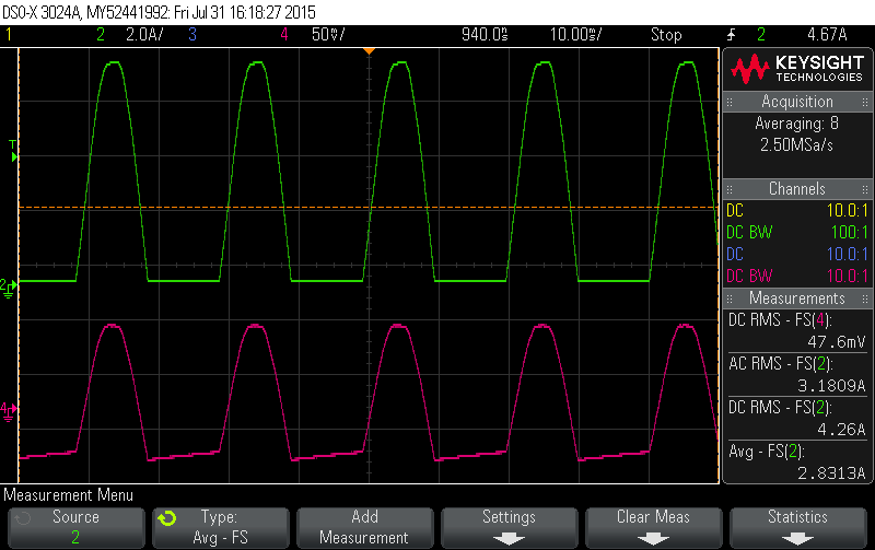
I’d second that. A cheap hair-dryer on ‘LOW’ provides an excellent example of a beefy half-wave rectified load. I’ve attached a picture of what mine looks like. The Green trace is as measured by a current clamp, and the Pink trace is as measured by a CT (note where the zero-point for the Pink trace is via the ‘4’ GND signal off to the left). The CT is trying to keep the signal balanced around 0 and it’s the CT that produces that slow positive ramp during the Green flat-line intervals.
I’ve got an emonTX shield that I bought a few months ago to experiment with. According to the schematic, the shield uses the regulated 5V supply from the Arduino, which is also used to power the ATMEGA328 with the ADC. I can watch that voltage vary, especially when driving with USB power. I’m not confident that the 5v as eventually presented to the ADC in the CPU doesn’t vary from the 5v that is exported to the shield and used for a radio and one-wire as well as source for the bias voltage dividers will be the same. One ADC step at 5V is about 5mv. That’s why I like the idea of using the external Aref pin. I think those two 5v incidences can vary.
Beyond that, I like the idea of using 3 v, as the YHDC SCT013 CTs that I’m using can come with internal ballast resistors for a variety of current ranges, with resulting voltage output of +/- 1V at full scale. That maps pretty well to a 3v setup with 1.5v bias. The net result is better resolution from the 10bit ADC.
Another thing that I’ve found is that the “readVCC” code that uses the internal 1.1V reference to calibrate the Aref is not very accurate. At least on the Sainsmart arduino boards I use. I get results that are about 10mv off. I’ve taken to using a reference voltage regulator for my voltage divider and Aref supply. They don’t cost much for a “B” chip that will regulate to 0.4% or so (1.2mv). Every little bit helps. With a reliable fixed Aref from board to board, I think I can use standard calibration factors for the various CTs.
So I haven’t run this wave form through any software but here’s what I’m thinking: These are representations of the current in the circuit. I believe the digital filter, over time, will work the Ioffset value up to a balance point, creating a smaller “positive current” wave, and a pretty beefy square-wave like negative wave. Maybe when multiplied by the reference voltage the lost “positive” area is about the same as the new “negative” area, so it sort of self corrects - or at least stays in the ballpark. In any event, fixing the reference point seems to be the right thing to do here.
I’m not all that familiar with the digital filter in question so will leave that to others more qualified, but as a general comment to:
Yes if you work through the maths, for the purpose of calculating Real Power it doesn’t matter how big a DC offset you add to the current signal. You could add 200A to every current reading you take and it won’t show up in Real Power (provided of course there’s no corresponding DC component in your Voltage signal). Although it will of course show up big time in Irms.
That’s true not just for DC but also for any of the harmonics, provided there’s no corresponding harmonic in the Voltage signal. You can add a 200A 150 Hz sine wave to your current readings and it won’t change the Real Power calculation (but again, will show up in Irms). I’m making the rather optimistic assumption that your Voltage signal is a pure 50Hz sinewave and has no component at 150Hz. In reality, unless you’re doing it in the lab with a pure AC lab supply (or doing spreadsheet experiments) there will be some small 150Hz component in your grid Voltage signal which would cause some of that 200A to leak into the Real Power calculation, but typically not much.
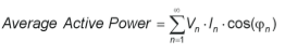
If you look at the frequency domain definition of Real Power it becomes pretty obvious why:
To the extent that your V is pure, Vn will be zero whenever n>1 so all the terms disappear bar the first one. As you add distortion to your V signal you bring those terms back and you’ll start to leak some of those current harmonics into the calculation. But on most grids Vn has a very small magnitude for anything but the fundamental frequency.
We use the supply voltage as a reference because it was asserted (I think by Martin Harizanov) that it was “more accurate” than the internal reference. This may or may not be an accurate statement, depending on how you define accuracy. The initial value is guaranteed to be within the band 1.0 - 1.2 V, so uncertain to the extent of about ± 9% as @dBC says, but I can find no data for the deviation due to temperature, supply variations, ageing, etc. It might well be that the internal reference is more stable than the external supply which, in the case of the emonTx, we have the data for. It’s relatively easy to correct for the initial uncertainty - the procedure is in one of the “Calibration” articles. Therefore, once calibrated, measurements made using the internal reference may well be more stable than those made using VCC as the reference.
Very much depends of course on the accuracy of the standard used in calibration.
What I’m trying to do is come up with a reliably calibrated standard to put on the shield, and use it’s output exclusively for the bias voltage dividers and External Aref. The goal is to end up with something that works reasonably well without a lot of calibration. If anybody has thoughts about how to calibrate the AC reference I’m interested.
There’s a page in Building Blocks that deals with the tolerances of the components that we use in the emonTx (and the Shield is mostly similar but runs on the Arduino’s 5 V supply, so that area is markedly different). If you require accuracy, you must calibrate accurately, it’s as simple as that. If you’re prepared to gamble, then hopefully - and a lot of the time this is indeed the case - the errors in the various components tend to cancel each other and you end up with a unit that’s well within the possible error band.
I obviously need to get a life. I’d completely forgotten about those - sorry, Bill.
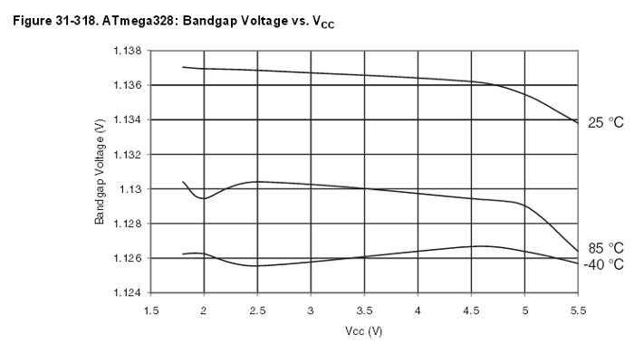
It looks as if the slope is about 1 mV per 2.5 V of supply variation (0.4 mV/V). Temperature is harder as there are only 4 points, and it looks as if it might have flattened out at around 25°C so my guess is the temperature variation is small (which is what I’d have expected if the designers got it right).
Putting that into perspective, the MCP1702 used in the emonTx has a supply regulation of 0.1 %/V, therefore the bandgap reference is already at 0.04 %/V before its VCC is regulated by the MCP1702. That 0.1 %/V will of course have load regulation added to it, but even so, the bandgap reference looks to be rather more stable than the supply even though the initial value is uncertain.
So not to get completely off topic, I’ve got a few questions about this thread.
I’m looking at the schematic of the emonTX and it has an MCP1754. That doesn’t appear to be much different from the MCP1702, but am I looking at the same basic thing? (Love the half-wave bridge power supply).
What started this off, i think, is a discussion of the stability and accuracy of the reference voltage to the ADC. I don’t see in my schematic where the 3.3V from the MCP17xx is being used for Aref on the ATMEGA328. Seems to me that there has to be a standard somewhere, and the MCP17xx is an order of magnitude more accurate than the internal 1.1 of the ATMEGA, so why not go with that and hard code in the 3.3Volts?
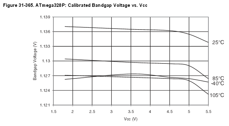
As an aside, i’m not sure I understand this bandgap voltage vs Vcc plot. On an ATMEGA2560, I’m getting 3.43V from the readVcc code that uses the internal ~1.1V reference. That’s what it is saying my external Aref voltage is. When I measure the external Aref with a pretty good meter, I get 3.34V. Maybe I need another cup of coffee, but that appears to indicate that the 1.1 reference is actually 1.07V. If I’m reading this plot correctly, it should be about 1.135V. Am I missing something?
I’ve not found the equivalent to Bill’s graphs above for the 2560, but I do use the 2.56V bandgap in 2560s and find that:
. it varies a lot from part to part (but always within 2.4 to 2.8V)
. it’s not particularly temperature stable (barely good enough for 10-bit operation, definitely not good enough for 14-bit operation).
Below is a plot I made of the 2.56V bandgap voltage with a 6.5 digit voltmeter over a 12C temperature variation. Like you, I too went with an external Vref because the normal daily temperature variations were showing up in my 14-bit conversions.