Hi,
What is a normal accuracy you’d expect on a YHDC SCT-013-000?
Has anybody got a calibration curve from 0 - 3kW I could look at?
I have an Arduino Uno running the test code from the website: Learn | OpenEnergyMonitor
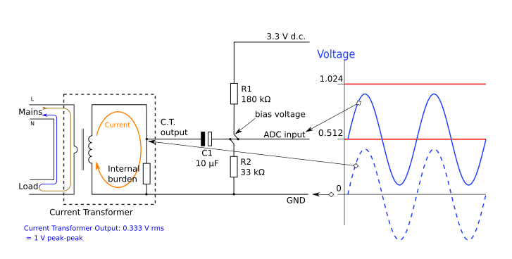
It’s setup with an 18ohm burden on the 3.3v line, running off laptop USB so power supply should be good & stable. I adjusted the RMS voltage to 240V instead of 230V as I’m in the UK and this is normal at my house.
But:
When testing with a hot air gun comparing the different settings to my home energy monitor I get a lot of discrepancy, like ~100% error below 2kW. Is this normal?
Real - Measured
0W = 150W (Seems odd that the zero crossing in the emon lib isn’t dealing with this?)
150W = 355W
400W = 780W
570W = 1017W
1115W = 1500W
2000W = 2000W (Gets more accurate at higher load, this 2kW is heat gun on full power)
2900W = 2900W (Kettle only)
4900W = 4800W (Kettle & full power hot air gun combined)
Questions:
If I’m using the Emon library I thought it would zero out much better than this to say 0-30W not 150W. I swear in one setup I was seeing this then it went back to 150W being is zero reading, no idea what changed.
Is there a port of the Emon library in python for use on a raspberry pi pico? Looks like they have high enough sample rate ADC converters now for this to work?
Thank you in advance
Tried:
-Definitely just clipped around 1 line wire, I made a special plug box to expose only this
-Cleaning my copper strip board with meths to remove flux that seemed to cause conduction issues
-The clip is definitely shut and well closed
-Testing on 5V instead of 3.3V (but didn’t change burden, no effect)
-Checked resistor values with multimeter, all good at 10kOmhs & 18Ohm burden
-Checked home voltage for the day at 242 Volts
-Calibrated using kettle known to draw 2.9kW via home energy monitor - increased current calibration from 111 to 118.169.
-Changing the sample number on calcIrms from 1480 to 5000 to 10000 - no visible change in error just smoother and more averaged readings.