Even tho I am trained in EE, I lack experience, and im just writing what i am thinking, so dont take what i wrote way to serious, (your work is a great job), and most of your assumptions are on the spot
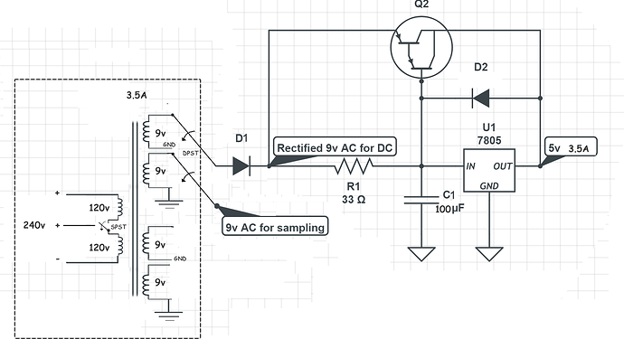
I drew the schematic in a rush and edited by hand some components, (since the online libraries don’t have them all), and left others with the default values (C1), but allow me to amend my informality in order to show what i was thinking and how i intended to show how the circuit works, this time using real components and values to amend my rushed work and dig a little bit further
The input transformer is supposed to be a Multiple Winding Transformer these kind of transformers can have multiple inputs and outputs, the primary would have 2 coils, in series that can be interconnected via a SPDT (switch), this way you can easily go from 120v to 240v (in parallel) by placing a small interrupter in the case, however, as a result of the primary doubling its value we would be forced to have up to 4 secondary coils, via a DPST
As you said, All the outputs would have to be grounded (i had little space do draw more grounds) the custom made transformer that will have 4 outputs (coils) in the secondary winding, for both cases 120v and 240v
The 1uF should not be there, i added at least 100uF otherwise the ripple voltage would just cause havoc all over the place
DC bias would be added with a voltage divider, 2.5v for a 5v waveform, or 1.75 for 3.3v
A 750mA transformer to feed both the ESP and the circuit, doesn’t sound that crazy, given you have the time and will to do/get them, you wouldn’t need the darlington array above the regulator by using a 1A VREG
It’s probably easier to just have 2 versions, one for 120v output transformer and another for 240v, but theres a lot of unused PCB space due to the amount of 3.5mm connectors, reducing the size or placing the 3.5mm connectors on both sides of the board should reduce the costs
