Why dont the emonTX, emonPi and IoTaWatt have an SMD Transformer on the PCB?

Its been a long time since i wanted to ask this, since this has been bothering me since i got here, it MIGHT seem more convenient to have an external 9v AC transformer (since you can replace it or switch between USA / UK standards) but this kind of transformers rarely fail, in the case of my emonTX due to lack of power to power up a bunch of sensors I ended up plugging both, the 5v USB SMPS and the 9v transformer

Isn’t it just cheaper, safer, simpler to just place an SMD transformer on the PCB and use it to feed both circuits AC and DC?

In the case of the emonPI add a 5v 1A linear regulator with a darlington array in parallel to feed Raspberry

I assumed this would become a feature overtime, but i noticed IoTaWatt followed the same design guideline, making the 3 hardwares more expensive overall, but im kind of clueless of why, can anyone explain why?

Speaking strictly for IoTaWatt, my considered answers to those questions are No, No and No.

But I’m intrigued by your assertions. Could you build such a circuit, with 5VDC output and 9Vac output, to demonstrate the feasibility? I’d be curious to see the assembled cost of the parts to do it and how those components, particularly the transformer, could fit on the IoTaWatt PCB inside the enclosure. Of course it should work in both 120V and 230V countries and be able to pass UL and other safety standards as the wall transformers do.

After, reading your post, trying to draw a custom switchable transformer (ala CPU power supply) that might as well not be commercially available, I believe, I am ready to help bring down my own statement

What i asked became a post when i was looking for the SMD transformers I just noticed I forgot about currents, and while trying to propose one, I just noticed the highest one I could find there was a 200mA one, so no way it can feed the entire circuit (at least the emonPi)

Another good point, as you said, having the transformer inside the device would put it into a different category as an electrical instead of an electronic appliance with a different norm making it harder to Cert

But anyways here goes the circuit, hopefully it will help explain what i was thinking, the entry it’s supposed to have both windings 127v added together via a SPDT, with this circuit ideally digital and analog ground would already have their own grounds to reduce EMC, the schematic is missing EMI filtering and protections.

BTW i know the certification norms of Mexico (NOM-001-SCFI-1993) but which one is the equivalent for the US and UK? I know the answer its UL and CE ( but what number? so i can read them)

I’m not trained in Electrical Engineering, so correct me if I’m wrong:

  • The transformer would have to have two independent secondary windings, not a center tap. That’s not clear in the diagram, but it looks like you use a center tap (effectively) for the AC sample and the 18V potential input to the DC power supply. The way I typically do it (and I don’t know another) is to sit the 9VAC on a DC bias. I don’t see how to do that when one side of the AC is connected to ground.

  • I’m suspect at the capacity of a half-wave rectifier with only a 1uF capacitor to carry it through the 10ms off cycle (50Hz). Especially at 500ma. (The specified DC power for IoTaWatt and needed when transmitting WiFi).

  • Given that it did work, how do you think taking all that power from half of the wave would affect the integrity of the AC sample as a proxy for the AC line?

Even tho I am trained in EE, I lack experience, and im just writing what i am thinking, so dont take what i wrote way to serious, (your work is a great job), and most of your assumptions are on the spot

I drew the schematic in a rush and edited by hand some components, (since the online libraries don’t have them all), and left others with the default values (C1), but allow me to amend my informality in order to show what i was thinking and how i intended to show how the circuit works, this time using real components and values to amend my rushed work and dig a little bit further

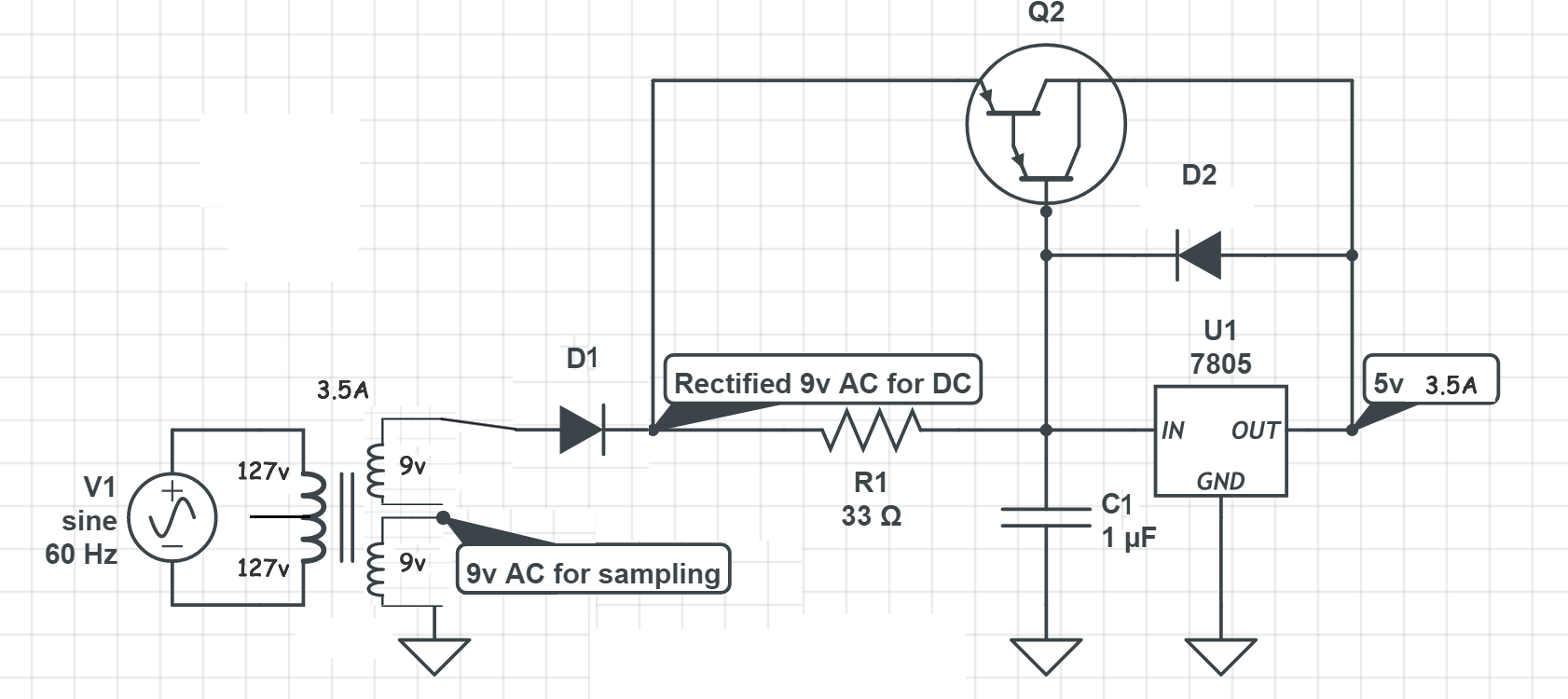
The input transformer is supposed to be a Multiple Winding Transformer these kind of transformers can have multiple inputs and outputs, the primary would have 2 coils, in series that can be interconnected via a SPDT (switch), this way you can easily go from 120v to 240v (in parallel) by placing a small interrupter in the case, however, as a result of the primary doubling its value we would be forced to have up to 4 secondary coils, via a DPST

As you said, All the outputs would have to be grounded (i had little space do draw more grounds) the custom made transformer that will have 4 outputs (coils) in the secondary winding, for both cases 120v and 240v

The 1uF should not be there, i added at least 100uF otherwise the ripple voltage would just cause havoc all over the place

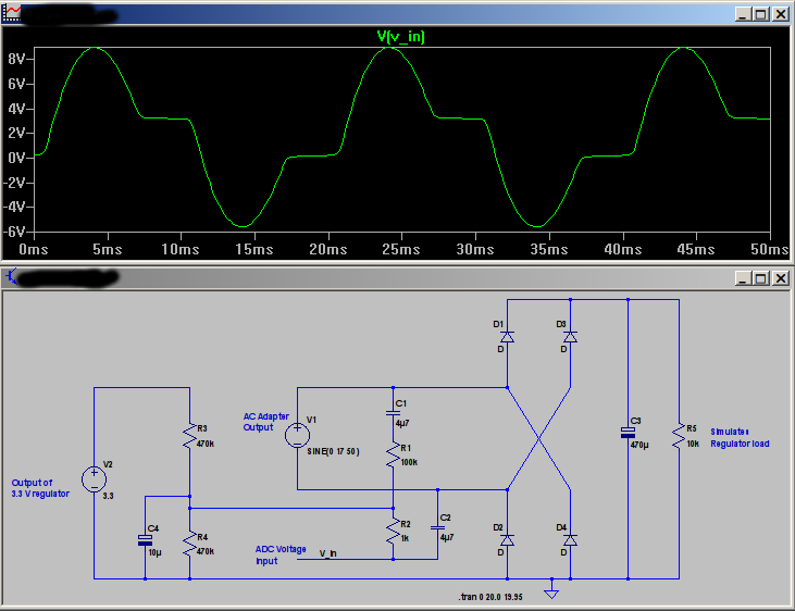
DC bias would be added with a voltage divider, 2.5v for a 5v waveform, or 1.75 for 3.3v

A 750mA transformer to feed both the ESP and the circuit, doesn’t sound that crazy, given you have the time and will to do/get them, you wouldn’t need the darlington array above the regulator by using a 1A VREG

It’s probably easier to just have 2 versions, one for 120v output transformer and another for 240v, but theres a lot of unused PCB space due to the amount of 3.5mm connectors, reducing the size or placing the 3.5mm connectors on both sides of the board should reduce the costs

I believe there isn’t an issue with adding a transformer onto the PCB for emonTX - however it then exposes the end user to high voltage mains instead of a “safe” output of a pre-approved AC-AC adapter.

If the community were encouraged to deal with mains voltages on a DIY basis all sorts of problems could occur and potentially life changing events - and I expect the OEM folks don’t want any liability for that.

That’s correct. To be able to use the incoming a.c. as both the power supply and the reference, and unless you accept the limitations of a half-wave rectified supply (the reservoir capacitor has to keep everything running for a whole cycle, not half of one), then you must isolate the two. There are three ways to achieve that, either a second transformer, two separate secondary windings on one transformer, or an op.amp. with completely floating inputs.

That’s where the op.amp. comes in. You use it to measure the true difference between its inputs, and mix in the standing bias at the same time.

There’s no chance of that working. The sum you do is: charge into the capacitor (Q = I × t) must equal the charge out to supply the device. That is 500 mA × 20 ms = 10 mC. The charge in comes via D1, and that conducts only when the winding voltage is greater than the capacitor voltage, which is for a couple of ms, say 5 at the most, per cycle. So you draw 2 A from the transformer for 5 ms (probably more for less time in reality). The capacitor must supply that and still maintain enough voltage for the regulator to work. That then gives you the size of the capacitor (C = Q ÷ V).

Badly.
What is the source impedance of the transformer? By how much will the voltage drop when you try to draw 2 A? Even with two separate secondary windings, the additional current will reflect back into the primary winding and still be seen by the other secondary (but to a lesser extent, because you’ve removed the IR drop in the copper of the secondary winding).

You will not need 4 secondary windings. You run the transformer at the same flux density when running on 120 V or 240 V. The usual way this is done is with two 120 V primary windings, which you connect in series for 240 V, and in parallel for 120 V. That way, each winding runs at the same voltage and carries the same current, and you have the same number of primary ampere-turns, whatever the configuration.

@Goat
I don’t see why you limit yourself to a half-wave rectified supply when you have two secondary windings. If you have a centre-tapped secondary winding, you can still have full-wave rectification and monitor from the same winding. But as I wrote above, with only the ends of the secondary winding available (as with an a.c. adapter) you can only use a full-wave bridge rectifier when you isolate the power source from the sampling source. Without isolation and without a centre-tapped winding, you must limit yourself to a half-wave rectifier. To see why (and why not), you must think of the rectifier diodes as switches that connect each end of the winding to the positive and negative sides of the capacitor alternately (and for only two short periods in each cycle), then think what that does to the voltage you’re trying to tap off to measure. And remember, to calculate real power, you need the full mains wave with a known phase relationship to the real mains wave.

1 Like

@overeasy, I was agreeing with you. I was simply pointing out to @Goat the mechanism whereby the integrity of the sample is destroyed.

If I look at a harmonic analysis of the output voltage of the standard a.c. adapter running a standard emonTx, I can see the second harmonic pop up and down as I power it either from the a.c. adapter or the 5 V. And the emonTx draws much less current than the adapter’s rating.

If my memory serves, there’s a discussion in the ‘Archived’ forum about the shortcomings of small pcb-mounted transformers.

OK, IThat’s what I thought a few days ago when you first posted, but it bubbled back to the top this morning, I think from an edit.

From my perspective, the original question is a slam-dunk right after he expresses his afterthoughts about the cost of the transformer. This is a recurring question that has digressed before into argument. It’s nice to see it resolved so fast. So what I’m trying to avoid is having the thread appear to actually be a discussion that has technical merit. Better in my opinion to be a “never mind”.

We could go on all day finding fault with his design, which he appears to have thrown over the wall for closure. I’ll give him a pass on that.

I’ll remove the post.

Sadly, you’re right that this is a question that recurs every few years. Possibly before your time here, there was a suggestion, by someone who shall remain anonymous, in which they used non-polarised electrolytic capacitors to “isolate” the voltage reference from the supply on the a.c. side of the bridge rectifier. What actually happened was one of those capacitors and part of the divider was in parallel with one of the arms of the bridge rectifier.

Here’s my simulation and the resulting “sine wave” for the mains sample voltage: