Im still working on how i will connect my monitoring to the gensets.
im from the Philippines, our frequency is 60HZ, the power of the generator will depend. but it will range form 150KW to 1MW, voltage output will be 480V and its 3-phase.
in general terms, yes, the genset will be the one to supply power.
With those sorts of power output, I think the main connections to the generator will be in a cable box or even busbars.
You’ll need a measure of both voltage and current.
First, I suggest you check the instrumentation of the generator. You might find that there are current transformers already fitted that can be used to give you a measure of current, but of course if you do this, you must take care that the operation and protection of the generator is not adversely affected.
The voltage will be the same (ignoring cable losses) throughout your system, so it should be possible to measure the voltage anywhere that is convenient.
If you need your own c.t’s (which is the safest), then our standard c.t. will not be suitable. Take a look at the “Use in N.America” page where you should find current transformers that are suitable for our emonTx or an Arduino.
If you are connecting via a cable box, you might be able to fit the c.t’s into the cable box of the generator, or in the incomer section where the generator feeds into your switchboard. It’s difficult for me to suggest a place without seeing your installation, and that’s not possible. You will have to look to see if you can find a suitable place. You’ll also need to arrange a voltage to neutral from each phase, so that you can calculate power. Again, the switchboard is possibly the best place to take that from, as you’ll need to have the proper protection in place. A standard small transformer of the appropriate primary voltage and around 9 - 12 V output should give you an acceptable voltage sensor.
[Please remember, the only information I have about your system is what you have written here, so any advice I give is based on that.]
what are my risks if I try to tap in the instrumentation of the generator.?
my colleague said that there might be some feedbacks if I try to tap it there.
is it possible to use a standard small transformer of around 9-12V with that kind of current and voltage?
well i have their technical specs here. its just that i really don’t know where can i tap my monitoring without harming the genset controls and self monitoring.
As I wrote above, ignoring the voltage drops in the cables, you have the same voltage system-wide (until you go through a step-down transformer of course), so you can monitor the voltage at any point on the 480 V system.
So yes, you need three small transformers with a 277 V primary winding (if you connect them line-neutral, which is the preferred way as that takes care of the 30° phase shift between the line-line voltage and the current) and a suitable secondary voltage - the exact value of which doesn’t really matter as you adjust the voltage divider to suit. The current drawn from this is insignificant.
its Okay Robert. I really dont mind. Im really a mechanical engineer. and my knowledge in electrical engineer is really not what you expect. Im working with my colleagues, 1 electrical and 1 electronics engineer. were all new engineers without much experience what so ever. thats why we need help.
can you tell me where can I tap in the genset that will not effect its operation and its selfmonitoring systems.?
If you connect on the main output - via suitable fuses or circuit breakers, a voltage take-off should be fine. Elsewhere, I can’t tell you without a full circuit diagram - and maybe even a set of mechanical drawings. With those, it would be easy; without, it’s almost impossible. You will need to do some investigation.
Do you only need to get at the voltage, or current as well? I’ve been assuming that you need to put current transformers on the output to measure the current.
How does the genny connect into the rest of your system? I would normally expect it to feed into a switchboard via an incomer, which would be a switch - probably a circuit breaker with suitable protection, and a means of interlocking if there’s another incoming supply from somewhere.
I’ve elevated your permissions here. It might help if you can post pictures of the controls & terminal box of the generator, and of the incomer - or wherever it feeds into your system.
yes, I need to measure the voltage and the current. and we will use a non-invasive current transformer.
the generator will be connected to the grid. the generator output 480V is seperated by a circuit breaker and will go through a step up transformer, and will come out as 13.8KV. i dont have the specs of our circuit breaker. but the genny’s voltage output is 480V and power output ranging form 100kW-1MW.
sorry cant provide you any pictures, because I dont have any of them.
The best way to tap off the voltage would be to have busbar fuses on or close to the main terminals, but it’s likely there won’t be room for anything like that.
Failing that, I think you need to add a suitably-sized box next to the generator’s main output terminal box. In it, you need 3 fuses or circuit breakers rated for the generator voltage and with a breaking capacity of at least the generator’s maximum output. However, the trip current rating should be the lowest available - likely to be around 5 A. These should feed the three small voltage transformers that give you a safe isolated low voltage to feed into your monitor. You will need high voltage cables from the main terminals to the fuses/breakers, these will be exposed to the full short-circuit current of the generator should there be a fault, so you need to keep the cables short, well supported and mechanically protected.
If you can arrange an earthed metal barrier between the high voltage cables/breakers and the transformers, then it should be safe to mount your monitor in the same box, bringing the c.t. cables in via the same route as the voltage cables, but well insulated from them. I’d consider substantial overall sleeving in addition to the normal insulation.
The reason for all the caution is vibration from the diesel engine. In the event of a fault, the fault current is likely to be a few thousand amps before the generator’s protection operates, and that could cause a lot of damage. Plus, if there was a short between the h.v. and your monitor, the monitor and everything connected to it would be live until the fault cleared; so you need to be aware of the danger.
I think that’s a red herring. You can feed your monitor from the genny, from another quite independent mains supply, or from batteries. I am confident that tapping off maybe a few tens of milliamps won’t affect anything. Unless you feed the output of your monitor back into the generator controls, I can’t see a mechanism for monitoring to affect the generator. You must leave the generator’s AVR and speed controls alone, I’m sure that the manufacturer knows what he’s made and has properly addressed the control and stability issues.
@Dave
I didn’t see that mentioned in the sales glossy, so I couldn’t assume anything.
Has anybody thought about interfacing with the generator? Via ModBUS instead of tapping all these analog points from the panel?
99% of all gensets have modbus capability out of the box. An RS485 2-wire twisted pair wire is typically is what is used, and to make it simpler, convert the RS485 to Ethernet adapter to make it easier to integrate into emoncms.
I don’t know if emoncms can talk modbus but I do know home assistant can, then use MQTT to publish to emoncms for data logging.
Instead of messing around with tapping analog signals, an interface will be able to give you all the voltages per phase, Amps, any faults of the genset, a lot more information, Etc.
We interface to gensets here in the US daily.
A lot of the ATS “automatic transfer switches” also have modbus capability for breaker position etc.
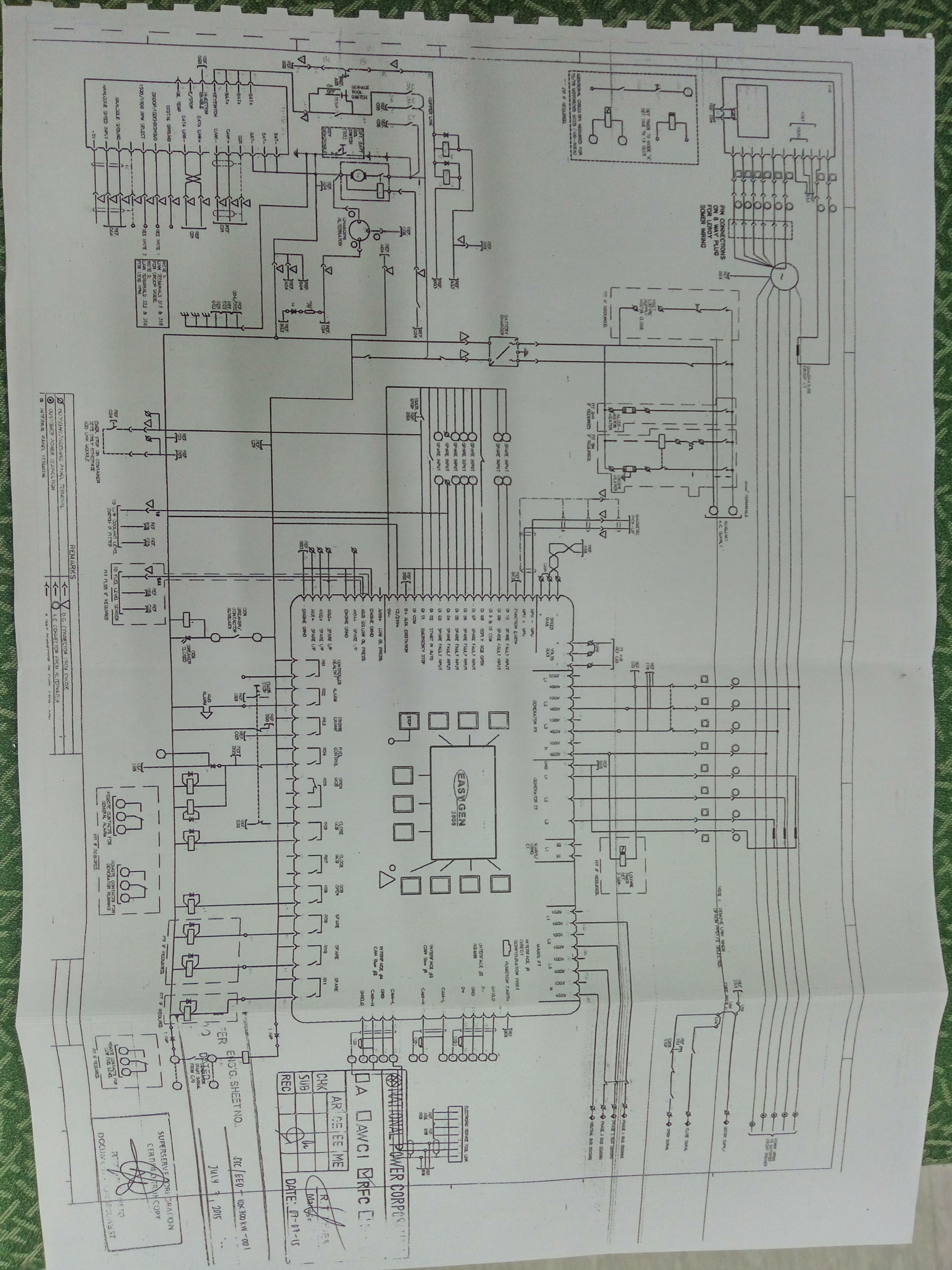
Edit: @cvkjason, what control panel do you have, usually the FG Wilsons ship with a power wizard panel, but importance is what version. Can you post a picture of the panel you have and any stickers of the control panel?