Thanks @TrystanLea for the introduction, and look forward to showing the emonPi3 and hearing anyone’s feedback or ideas. As Trystan said, looking at start of 2025 to have tested hardware available for purchase so there’s time to make changes in the meantime. Here’s a quick summary, and I’m happy to break it out into a separate thread if it would be easier to follow:
The AVRs are old and expensive. @Robert.Wall has done a lot of work to make it work with 3-phase and 12 channels, but it’s really at the limit. This also leads to a lot of “versions” of the firmware, rather than a single configurable option.
Much more performant and much improved peripherals (pseudo-differential ADC, serial modules, DMA, flexible timers/events etc).
The SAMDs have a wide range of parts with various pin counts, peripherals, and cores (Arm M0+ and M4F) which all share common software. This makes making variants (Pi3 vs Tx6 etc) much easier.
Can be reprogrammed through USB using UF2 (drag-and-drop from your OS), rather than needing an external device. Normal configuration is through USB (not yet implemented) or UART serial.
@borpin - the ESP32 doesn’t have enough ADC pins (and its ADC isn’t great either), has much poorer peripheral support, and isn’t available in as many variants. It’s great for the WiFi part (obviously), so I’ve designed the system to abstract the data transmission side from the data collection/processing side (i.e. the user can choose RF, WiFi, full-fat Pi attached, ethernet etc)
Added and revised features
Compatible with existing OEM configurations
Anti-aliasing filters for all inputs (sampling is at fixed rate, rather than dependent on the number of channels) with oversampling
Revised the referencing and biasing to minimise noise from supplies
Hardware zero-crossing detection
Onboard ADC calibration for gain and offset
Full support for additional sensors on OneWire and I2C interfaces
Software wise, I’ve redone things in plain C rather than using the Arduino framework. The rationale for this is that Arduino hides a lot of details from the user (which is fine!), but once it’s stretched it is very difficult to find resource conflicts (e.g. timer usage) and do “real” debugging, rather than just printf. The firmware is designed to be compatible with the existing OEM setup. There is Arduino and CircuitPython support for the SAMD series, so that option remains for those that want to use it.
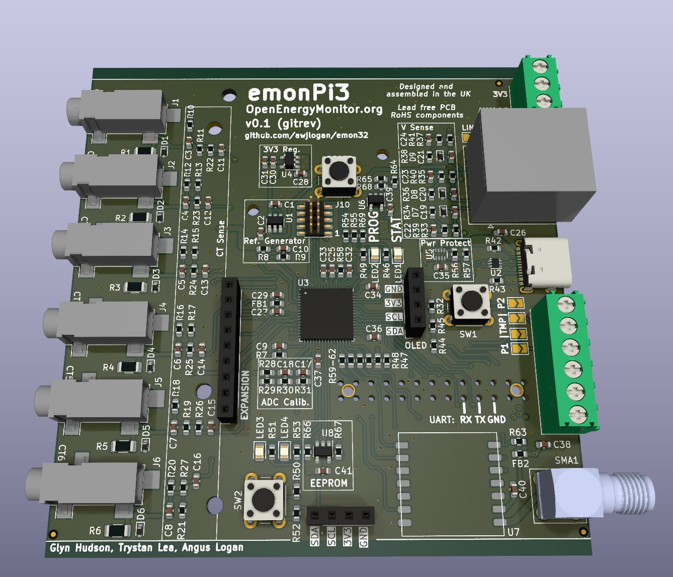
You can get the KiCad board files here, and the firmware is available here (best to look at the pi2-0.1dev branch). Please let me know if you have any comments/suggestions/questions
(There is a small “low cost” version in there as well. I think it’s too small - something to review now that the emonPi3 is a bit more developed/stable.)
Are the solder bridges for the pulse and temperature sensors absolutely necessary? Could the selection be done in software?
Wedged in between the push button and the terminal block, they are inconvenient to get to. If they are needed, are they spaced out as much as possible?
Also, does the screen need any mechanical support? Will the header be enough to hold it in place - bearing in mind the abuse they received during shipping? We are currently soldering the screen onto the emonPi2 because of this. And when you solder the screen onto the board directly, the distance to the Pi’s GPIO headers is uncomfortably close.
Hi @Gwil - thanks for the message, and glad you like it
I did have these on the bottom side to avoid the components on the top layer, but @glyn.hudson pointed out that this will interfere with wave soldering (has to be taped off at added cost), so I moved them back to the top. Ideally, it would just be a software select but the OneWire bus needs a strong (~4K7) pull up to function so we can’t use the switchable built in weak pull-ups. Would a physical jumper, rather than a solder bridge, be preferable? Still a little fiddly, but more easily reversible.
Other option: there are 3 spare pins on that side (I’ve used them to allow firmware to determine what version of board it is on, but that’s not critical), so the strong pull ups could be conditionally connected, which would achieve the desired result. Added to the to do list to look in to
It might be possible to squeeze in an extra mounting hole between the screen header and the 26pin RPi header - the routing for traces on that side are not too critical. Will see what I can do!
I still think the option for these additional sensors are redundant in the current environment. 10 years ago, yes, now less so. Save on the screw headers etc.
Could the RF be pluggable and optional? Again, in current environment, this is largely for backward compatibility rather than a mainstream requirement.
How well do multiple units work on same RF network. There are many threads here of issues with interference between the RF devices.
I’d be interested to know what a unit, stripped back to just 12 channel senors, a cheap enclosure and an ESP32 for comms would cost compared to a fully featured unit.
We are seeing a lot of demand for the EmonTH. We think the ease of integration that the radio brings does add a lot of value for folk. Having experimented with WiFi sensors in my own home I’ve always found that they drop off after a period of time and require either a reboot or a router reboot to get them back up and running. I ordered that mini router you recommended @borpin and that also ended up giving the same issue. In the end I pulled up the carpet and floor boards and routed hard wired Ethernet to the location with the heat pump monitor in our house and it’s been nice and stable since.
There’s also the benefit of not having to reconfigure all your WiFi sensors when you change a router.
My EmonTH temperature sensors have been rock solid on the RFM69 radio and I like the simplicity of integration. That’s my $0.02 in defence of the RFM69
Glyn and I did debate the cost of the emonTH vs alternatives before bringing it back in stock, we cant compete with the price point of many of the alternatives but the demand is always strong when we have the emonTH in stock.
I guess a Zigbee USB receiver and Zigbee sensors is another route that does not rely on WiFi.
I can see you’ve addressed the clearances on the Pi’s mounting holes.
If feasible, that would be great. Personally, I don’t think jumpers are necessary or desirable if not.
The other issue is that the current push button is extremely vulnerable when the board is outside of a case. It also makes it awkward to assemble the case: you need to attach it to the front plate before putting it together. I actually think it is still somewhat vulnerable inside the case.
@awjlogan The emon Pi 3 looks really good I very much appreciate all the work done by those involved.
Some comments and questions -
Is there enough room to fit a solder link in series with each burden resistor (R1-6)? This would allow 6.8ohm burden resistors to be permanently fitted, and the links left open. If a user wanted to re-use his 50mA CTs because of cost, or because they’re already fitted deep inside his consumer unit, then he just has to close the links. 50mA x 6.8 ohms = 340mV so it would also need a small change to the calibration values.
Would it be possible to move one of the DS18B20 inputs to CN3, so the user could have two pulse inputs and a temperature input? The two pulse inputs would be used for counting the optical pulses from the mains and solar meters for calibration, while several temperature sensors could be attached to the DS18B20 input.
From the schematic, it looks like the RFM69 MISO, MOSI, SCLK and SS can be driven by either the SAMD or the Pi. However the RFM69 IRQ and RESET can only be driven by the Pi. So when the board is an emonTx6, they can’t be controlled. What is the reasoning here?
Again on the RFM69, the RESET button will reset the SAMD, but not the RFM69, although I don’t know if this is necessary.
Changed from the solder pads to software control for the OneWire and pulse selection. Much nicer, and there’s a spare pad to keep the board version available. I’ll update the firmware when I have a bit of spare time.
Looking at my OLED module (some cheap eBay SSD1306), it will be very difficult (if not impossible) to find space for mounts. To the left, both holes are directly over the microcontroller and on the right, the bottom hole overlaps the 26 pin header. The top right pin might be able to squeezed in, but will depend on dimensions of the OLED module you use.
Re. the push button stem, this could be solved by using a short stem button and having the presser integrated into the case, rather than then stem protruding. If you have access to the 0.1-dev board I sent to OEM, you could experiment with that?
The screw headers are a minor cost, more a space consumer than a cost consumer! From a backward compatibility standpoint, they are needed and also would be useful for the heat pump system. Internally, one could add an I2C temperature sensor (bottom header).
Multiple uncoordinated RF devices is a generally hard problem, not really restricted to a particular board design. ALOHAnet is the canonical solution, but requires independent Tx/Rx channels, which we do not have. One solution might be to have the base provide a 1 Hz (for example) tick to synchronise devices, and then use the node ID as a time offset for transmission.
A pluggable RF/ESP32 system would be technically feasible, but the big issue from a vendor (i.e. OEM) perspective is stock keeping and maintaining multiple product options. If N emonPi3s are made, how many RF and ESP32 boards are made? Due to the volume cost advantage, it’s generally cheaper to provide one built in default option as standard. One of the really big advantages this system has is the greatly improved processor with multiple variants, so at least the software side of things is simplified - one firmware to rule them all! I will, however, add a header to the next revision that will take an ESP board (hopefully an off the shelf one, but possibly a very small custom board).
Cost wise for a stripped back system, I can do a spreadsheet exercise to see for the PCB alone
Agreed, the big advantage of using the RF units is the range and reliability. I think for at least this version, it should remain as the default backward compatible option.
Easily space for a link. However, why use a link when the space could be left unpopulated and the user could then fit their own burden resistor? That way they have control over the resistor value, rather than having 6R8 only. The maximum full scale input is 1.024 V peak-to-peak (Incidentally, I have some ideas around per CT gain using DMA to reconfigure the ADC on the fly, but first things first!). Potentially could be underneath the board for ease of access, rather than having to work around the jacks.
CN3 can’t be used for OneWire as the analog input has the anti aliasing filter (R7, C9) on the pin (and no pull up available). The best way would be to configure CN1 for OneWire, CN2 for pulse, and also use CN3 for pulse (I can show you how this would be done in the firmware if you’d like). As the pulse sensor is edge sensitive and has a blank period, the AA filter won’t be an issue.
The RFM arrangement was taken directly from the emonPi2, I did wonder about that. @TrystanLea - any memory as to why that is like that, pin constraints? It can be arranged to have those connected properly, I’ll experiment with a module here, but almost certainly makes sense to do that!
The RESET button is for the SAMD only. A single press resets the device and a quick double press puts it into USB bootloader mode (indicated by the PROG LED slowly pulsing). The user can also do a soft reset using a command over the serial link. With the suggested change to connect the RFM reset to the microcontroller, we can just do it in software at startup.
(NB, I’ve made a new branch, pi3-0.2, for the next PCB revision which I’ll try to keep up to date.)
@awjlogan Thanks for the quick reply. My comments are (in order)
Burden resistors. As for 50mA CTs, I was assuming that most users of current CTs would either be using the traditional YHDC 50mA blue 100A SCT-0013-000 split core CTs or the solid core 50mA Talema/RS Pro 20/40/50A range, hence the choice of a 6.8 ohm burden resistor. From memory, I can’t remember other CTs being recommended.
From my own experiences, I think it would be much easier to put a dab of solder onto a link than install a SMT resistor between the jack sockets.
And buying just 6 or 12 SMT resistors from Farnell or RS would involve minimum order quantities of 10/100 units and there would be a small order handling charge of £9.99 or £6.95 respectively. So having the resistors already on the PCB would be a big financial advantage!
Sorry, I missed the anti aliaing filter on CN3, but from your reply, there is another way to get 2 pulse inputs and one temperature input - so that’s good!
RFM connections and RESET. I asked about this because I have seen RFM69s get confused and apparently lock up. It would seem a good idea to connect the reset line for use in case of emergency!
The RESET button - Sorry again - I didn’t know it had two functions, with a double press to start programming the SAMD chip.
I’m the exact opposite - I’d much rather solder a big SMD resistor than a bridge I will add the extra jumper in and populate the burden resistors by default, though - much cheaper to have it onboard rather than having to order an extra bag. For future reference, eBay is a good source for small component orders, rather than trying to deal with the big distributors.
I’m not sure it will be a regular use case, but I’ll make a note on how to do it - essentially it’s a remapping of the pins and External Interrupt Controller (if you want to look in the datasheet). In the firmware, the pin mappings are a set of defines and arrays in board_def.* - you need to remove the analog input from the ADC array and add it to the pinGPIO_In array. (Just looking at it now, the ADC pins haven’t been named - I’ll add the logical mappings…).
No need to apologise, I’ll make sure it’s clear in the documentation
Wow this thread has done a sharp U-Turn from my negative start to a very bright future!
Overall I think backwards compatibility is important if it is not cost prohibitive, I agree the one wire temp sensors are less critical these days, but I have some on my hot water as part of diversion monitoring and if I upgraded would want to keep them on a EmonPi3
replacing an EmonPi1
Temperature measurements, I never started with EmonTH but I would share as a general recommendation what I am using in case it helps others - which is EocWitt who make weather stations.
You don’t need an entire weather station, they have a USB gateway GW1100/GW1200 that receives the 868Mhz (Europe) sensors and uploads to their cloud but also will integrate to Home Assistant. https://www.ecowitt.com/shop/goodsDetail/299 its about £20-25 on Amazon. The system supports up to 8 WH31 sensors that are around £13-15 on Amazon and report temperature and humidity, AA batteries last about 1 year before charging (Eneloops) outside and longer inside where its warmer.
You can of course start with a full weather station as well, but even if you just want temperature its not expensive option, the 868Mhz radio is reliable and the gateway presents to HA for integration in automation or dashboards.
There are various other sensors, usual wind rain etc, but also temperature of water (on a flying lead), soil moisture for the gardeners, leak detection lightening etc.
The sensors can be had cheaper from China, but the official Amazon store is price comparable when sale prices are available.
@awjlogan Thanks again for the reply, and for adding the jumpers and loading the burden resistors. Also for working out how to measure two pulse inputs and one DS18B20 input.
And thanks for the tip about component sources.
I hope all goes smoothly on the emonPi3 development.
Added the jumper option, you can see it on commit 62dad58. I took the opportunity to tidy up the schematic a little as well, breaking the repetitive CT front end into a hierarchy.
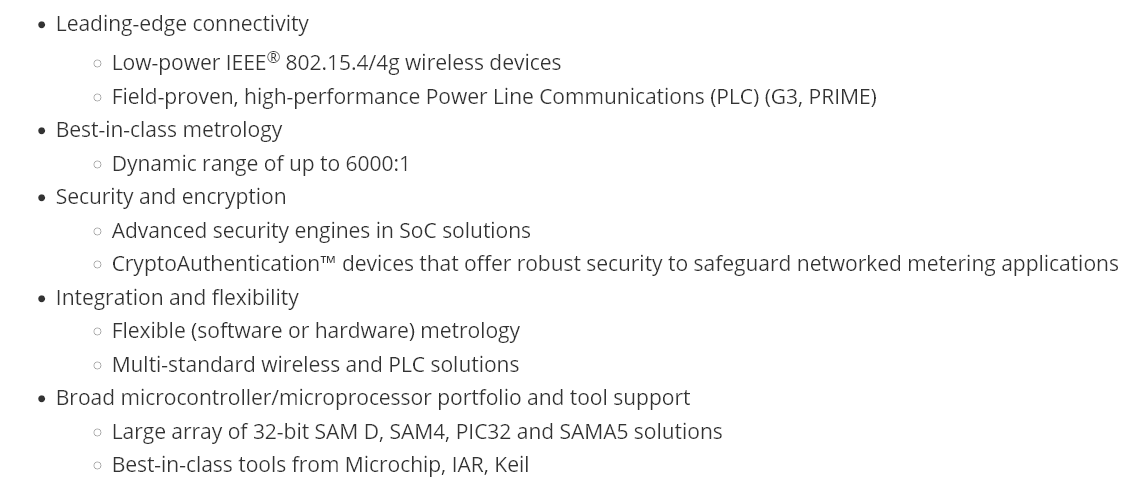
Yes, definitely considered but there are two main barriers: safety and cost. Generally, they are connected directly to mains voltages (see the application information). This means the safety and regulatory work is more intensive (and expensive) - I wouldn’t mind doing it for myself, but as an OEM product, it would not be feasible. And cost: they are 2 or 3 channel devices, whereas the SAMD used on the emonPi3 is capable of 3 phase, 12 CT input on its own. Of course, the ASIC solution is better specification wise, but I don’t think it works in this setting.
I was thinking more along the lins of what forum user John Deglavina did.
His device uses CTs, and an ESP32. Although it could have used other MCUs as well.
It’s capable of being expanded to 42 channels.
Ref:
and
(He sells this version for 55 USD, the one linked above for 75 USD)
If nothing else, some good info in the threads linked above.
Thanks Bill - nice reading material, and John has done a good job with it. In principle, it could even be extended further, but I suspect he’s run out of pins on the ESP I will certainly do some more reading - I think for this version, at least, it will remain with the microcontroller front end and processing, but there’s certainly advantages to the dedicated ASIC.