This seems to be brought up every now and again when people cant use the shop supplied CT’s. The advise given is to look at the America guidance. I have myself bought some non standard CT’s (DL-CT08CL5-20A/10mA 2000/1 0~120A Micro Current Transformer) which work well but was a best guess on if they would work.
From my research the difference specs quoted between the CT’s are as follows…
Size
Primary Current
Secondary Current
Output Voltage
Secondary Turns
Some CT’s refer to a 100a/33mV and others refer to 100a/5a.
My questions is what does all that mean and what should you be looking for when buying non standard CT’s?
Size.
Physical? You need a c.t that will fit over your cable (or busbar) and inside whatever enclosure you have.
Current? For indication and measurement, see point 2.
(For protection - OK, it’s unlikely that anyone here will be looking for a c.t. to operate a protective device - you need a c.t. that will operate the protective device under the worst-case fault conditions.)
VA rating? Often not directly specified, it determines the maximum output power of the c.t. It’s sometimes given in a roundabout way as a maximum burden resistance or a maximum voltage with a specified burden; and sometimes not specified at all (in which case, avoid).
Primary current.
Your c.t. must have a rated primary current as close as possible to, but more than, the maximum current that you expect to encounter. [This isn’t just my advice, it’s what the manufacturer will recommend too.] If you go too far above the maximum current that you want to measure, accuracy at the bottom end of the range suffers. All c.t’s are inherently inaccurate at very low currents (relative to the rated current).
Secondary current.
Please yourself. The higher the secondary current, the greater the power that is dissipated in the burden instrument, or more usually in our case, the burden resistor. The lower the secondary current, the more secondary turns are required, which usually means a finer wire gauge to keep the size of the winding down.
C.T’s are most accurate when working into a short circuit (because the output is a current and that is the minimum power condition).
Native OEM/Megni products are designed for a secondary current of 50 mA. If you want to use a c.t. with a different secondary current at your maximum primary current, then you must change the burden resistor. The emonTx/emonPi require about 1.1 V rms for maximum indication, with a 5 A secondary that would imply a 6 W burden resistor, and connectors and cables to match.
Output voltage.
Every transformer has a VA rating. Exceed that and the transformer is overloaded. In the case of a c.t., you exceed the VA rating by asking it to deliver a higher voltage, by increasing the value of the burden resistor. The result is increased errors, usually accompanied by waveform distortion.
Secondary turns.
Forget the turns ratio. If the manufacturer is up to his game, the turns ratio will be adjusted for each manufacturing batch so that you get the best accuracy for the current ratio over the specified range of primary current.
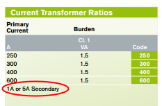
Traditionally, c.t’s are specified by the two currents, so a 150:5 c.t. will give you 5 A secondary current for 150 A of primary current. A 30:1 c.t will have the same turns ratio, but it will be a very different beast. A 2000:1 c.t. will give you 1 A secondary current for 2kA of primary current. The YHDC SCT-013-000 is 100A:50mA.
Current output or voltage output.
Some c.t’s incorporate a burden resistor inside the case. In that case, the c.t. acts as a voltage source and the output is specified as a voltage, not a current. Then it must work into a high impedance, otherwise accuracy is compromised. The emonTx/emonPi incorporate the burden resistor, so a voltage output is only compatible when that burden resistor has been removed. Both require about 1.1 V rms for maximum indication, so a 1 V output should be specified.
Split core or ring core?
If you aren’t qualified to break the circuit to install a ring core c.t, then you must use a split core one. But if you have a choice, a ring core will be smaller and more accurate, and cheaper too.
It’s how c.t’s are specified. If you’ve read this far, it should be clearer.
all of the above!
While we’re at it, a is the symbol for the multiplier atto (10-18). It should be A for amperes.
The rule is very simple, and in this order of precedence:
Units named after people have an UPPER CASE letter (Ampere, Gauss, Newton, Hertz, Kelvin, Faraday, Celsius, Joule, Volta, Watt, etc.)
Multipliers greater than one have an UPPER CASE letter. (Mega, Giga, but kilo is beaten by rule 1 - Kelvin.)
Multipliers less than one have a lower case letter. (milli, nano, pico.)
So two very common errors: Mhz is always wrong by rule 1, mhz is always wrong by rule 1 and probably wrong by rule 2.
Question: How do you calculate the burden resistor is you don’t know the amount of turns on the CT? Say if I wanted to use the following CT >> TAS-T36 250 /1A
1.1 Ohm !
So presumably you use the following formulae if you don’t know the current output and only know the secondary turns?
burden_resistor = (voltage / 2.0) / ((I_RMS * 1.414) / ct_turns
Yes, and 2 W power rating. And don’t use a 3.5 mm jack plug at 1 A rms.
I don’t recognise that! You must always know the secondary current - it’s how c.t’s are designed and specified, it has to be on the data sheet.
Each c.t. on that list will use exactly the same value of burden resistor.
Some (Chinese in particular) manufacturers seem to specify the primary current and a nominal turns ratio, from which I think you’re expected to infer the secondary current. If it’s the actual manufactured turns ratio they specify, then you don’t know the current ratio over the full operating range, so the accuracy they claim is meaningless.
(I was expecting you to ask, where does the 1.1 V come from? It’s the maximum rms voltage after allowing for a low 3.3 V supply, off-centre bias and all the other component tolerances, less a bit for headroom.)
Sorry yes you are correct, for that CT specified before, you need to put the burden resistor before the jack plug, install a couple of zenor diodes for safety and remove the burden resistor from the EmonTx or EmonPi
If you increase the value of your 1.1 Ω burden so that the combination of that plus the internal 22 Ω burden is still 1.1 Ω, then you don’t need to remove the internal one, 50 mA will flow in that, and 950 mA will flow in the external, now - 1.158 Ω - resistor.
In practical terms, forget about altering the value and adjust the calibration. You probably can’t buy a 1.1 Ω 2 W resistor anyway, it’ll almost certainly have to be 1 Ω or 2 × 2.2 Ω in parallel.
I’ve been meaning to speak to Glyn about rewriting that page for some time. While it’s accurate, it’s far simpler to calculate the rms voltage required first, assuming that the waveform is well-behaved (to give the value of voltage to aim for that I quoted above - 1.1 V for an emonTx/emonPi and 1.6 V for a 5 V Arduino), then work totally in rms values from there onwards.
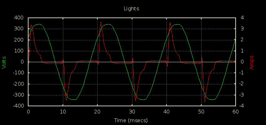
The ratio of peak:rms doesn’t have to be √2. For the wave that @dBC uses to demonstrate switching regulator-type loads, it is much greater, whereas your mains here in the UK is likely to be about 1.39 due to ‘flat-topping’.
In that case, Irms is 1.135A while Ipeak is 3.648A, so a ratio of about 3.2.
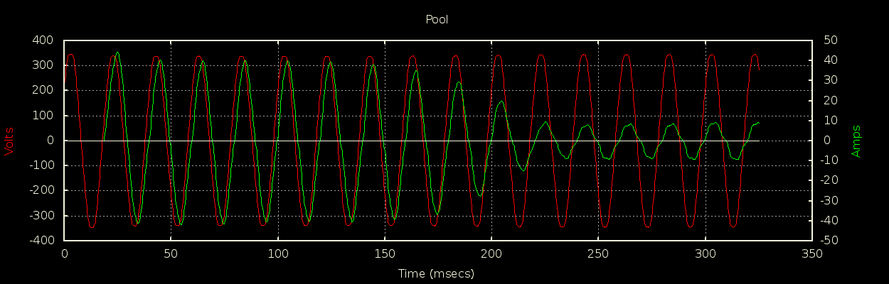
Another one to look out for is start-up current on motors. My pool pump draws somewhere around 5A once up and running. I wrongly assumed a 20A CT would be more than sufficient but was seeing serious clipping on pump start-up (for quite an extended number of cycles). Once I replaced it with a 50A CT I could see that the start-up current is up around 45A peak:
When you’re doing whole-house monitoring, the law of big numbers helps a bit to smooth some of this stuff out, but once you start putting CTs around individual breakers, it’s quite common for “unusual” behaviour to become the norm… non-linear loads totally dominate my lighting circuit, and big start-up currents do the same for the pool circuit.
Indeed. Yours is about 5½ times, which is about normal for something like that. That’s why I very carefully wrote
and partly why I mentioned c.t’s for protection, which have to not only survive but operate more or less correctly on fault level currents.
I know there are people who don’t understand and appreciate just quite how big inrush can be.
I remember a junior motor designer asking what would be the inrush on a tungsten projector-type lamp. I told him “Somewhere between 10 and 15, probably 12 - 13”. “12 - 13%” he said, sucking through his teeth. “No, times.” I said, and he had to hang on to my desk in order not to fall over. I should explain - the inrush he was used to calculating was due to the temperature rise in copper - round 2 - 3%, and so he thought 12 - 13% was a lot…
I have seen it mentioned a few times not to use a CT with a 0.333V output to get the 1.1V.
While seeing often other outputs ranges being explained with detailed explanations.
It might be obvious but, I need it explained please. TIA
This is to get a power diversion board setup properly.
Your question is unclear: what is it that you want explained to you? Why 0.333 V rms is less than one third of the voltage input range of the emonTx?
If your analogue input has a full scale input range of 0 - 1 V, then a 0.333 V rms output c.t. is fine. If it’s 3.3 V, like the emonTx and emonPi, then instead of a 10-bit digital number (0 - 1023) coming out, you’ll have 0 - 310, or a fraction over 8 bits.
But you can’t, and shouldn’t try to, overdrive a 0.333 V c.t. in order to hope to get 1 V out, by choosing one with a rating ⅓ of what it should be. It will saturate, the output waveform will no longer be a scaled-down replica of the input current, and your measurement will be badly wrong.
I may be incorrect in needing 1.1 volt. for power diversion with eMon TX, so 3.3 Volt is what you’re saying it needs to be.
Burden resistor is not going to get what is needed for 3.3V?
3.3 V is the absolute maximum peak-peak, given a 3.3 V supply. With an allowance for component tolerances and some headroom, the value I advise is 1.1 V rms for the emonTx, emonPi or any 3.3 V Arduino, or 1.6 V rms for a 5 V Arduino.
Has something been edited out of that sentence? It doesn’t make sense to me.
Again, this would be for a power diverter and running one of Robin’s sketches.
Let me try again, Can a burden resistor be sized such as to correct the voltage for a 0,333 V c.t. to achieve the needed output?
The c.t, specifically, would be a Magnelab SCT-075-000, with out internal burden, or else maybe another size SCT-075 xxx with it’s internal burden removed, IF that works the same way as the first one listed which has no burden resistor.
May as well ask this now too, Can any adjustment be had by editing some value in the sketch to achieve a desirable output?
No, because if the c.t. is a voltage-output type, the burden resistor is internal, and you have no control over its value. If the voltage is too high, you can lower it by adding a second parallel resistor externally, but if it’s too low, there’s nothing you can do.
Do you mean the SCT-0750-000? You can choose the “no burden resistor” option with that one, then have an appropriate value burden for your needs within limits. We’ve had discussions with Magnelab, so we know what those are. Their c.t’s are very conservatively rated. Specifically, Magnelab’s white paper says “Magnelab SCT-0750 Current Transformers can function safely from zero to 200 Amps. A 5 Amp unit will have an output of 0.333 Volt at 5 Amps and the same unit used at 200 Amps will have an ideal output of 13.33 Volts. The temperature rise at 200 Amps will be only a few degrees due to low current in the secondary winding. Therefore, an SCT-0750-005 (5 Amp unit) could be used at 200 Amps since the core does not saturate and the temperature increase is minimal.”
However, the 1 V option is close enough for the emonTx/emonPi, so I would advise that as it removes the uncertainty associated with your own burden. You will need to remove the burden fitted inside the emonTx/emonPi. Whichever option you choose, you’d probably need to change that component anyway.
You can alter the calibration by changing the multiplication in software, but if you don’t have the resolution at the very first stage of the process, there’s nothing you can do to get it back. It means that you will have larger steps in the output values, which will be particularly noticeable at low currents.
See if I have this correct? A Magnelab STC-0750-150 c.t. outputs 0.333 V at the factory rated 150A due to appropriate factory installed internal resistor value?
Note: With a DMM across the secondary leads it reads now at ~6.5 ohms.
If I had some insight as to how to surgically remove the Magnelab c.t.'s factory installed internal burden resistor then I’d be all set.
I have 10 of them and they were bought cheap, so, I’m not scared to bust into one to see and to find out what’s inside, if that could make it work.
I see from the spec sheet that the “No Burden” STC-0750-000 has zener diode to limit max voltage to 22 V, should this be added if/when removing the factory installed internal burden resistor?
From what Bill reports, the question is irrelevant. But I’ll explain:
A c.t. is a current source. It generates whatever voltage is necessary to drive the current it needs to into its burden. In the absence of a conductive path provided by you, the voltage will rise until it finds one - it may well “flash over” and damage itself in the attempt. The zener is there to hold the voltage down to a safe level if the burden is accidentally disconnected.
I went ahead and attempted to open one too.
I, same as you, found it difficult to not destroy it. But I will attempt it on another one with a different approach this time.
After having gained valuable insight and not wanting to giving up just yet I will be attempting this again.
So if I have success taking the factory burden resistor out of the c.t., Would it be best to add the new calculated burden resistor across the twisted c.t. leads rather than on the pcb location which is after the board plug in jack?
Thinking is, that at this location it would avoid having voltage rising towards a potential flash over from any accidental disconnection, as you described.