Hello,
I’ve been happily using emoncms on an EmonPi for around 5 years now. I’m pretty sure I have the CT clamps in the right place as the usage and generation readings seem to be correct. However…
We’ve recently changed our hot water system to be purely electric. The heat is stored in a Sunamp heat battery and during these winter months we are charging it off mains electricity on a timer. The issue I have is that when the timer kicks on on the diverter, the emoncms shows a negative reading.
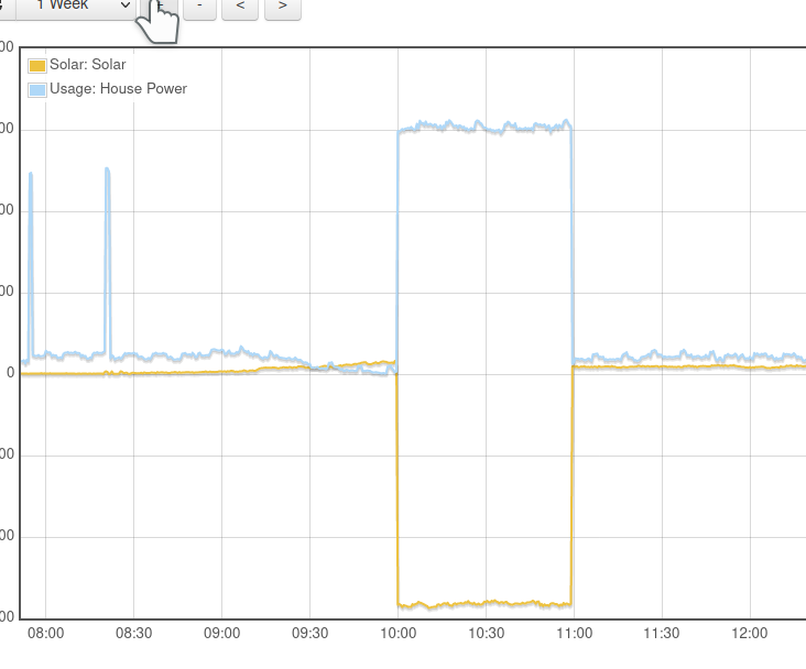
It’s puzzling though, My feed for “House Power” is equal to the amount being diverted plus the load from the house. At the same time, the “Solar” feed is negative to the amount being diverted. There is another cable I could probably connect a CT clamp to to read the amount diverted directly, however there are obviously only 2 CT inputs on the emonpi itself. Would I need to use the LED detector on the meter to do this properly? Is there another way using clever maths? Here’s an example from today. You might be able to see a tiny positive reading from the Solar feed (it was a cloudy day) and obviously the massive negative reading once the diverter kicks in.
The main issue with this is that it’s messing up the readings from in the Octopus Agile app, which has - up until now - given me fairly accurate readings on what I’m actually going to be paying for electricity on a daily basis.
Happy to post pictures of the positioning of my CT clamps and other various wires, but not sure what to post - to my untrained eye, it’s a bit spaghettified in there 
Many Thanks
Jerry
I was thinking of asking where each c.t. was located in relation to the meter, your consumer unit, the PV infeed and the heat (battery) store. That’s what we really need to know - a single line diagram (showing just the fuses/MCBs and line connections - forget neutrals and earths) showing how all these things relate. But I suspect from that, you might struggle.
The graph tells me that the Solar c.t. is also seeing the heat store power - is it that which you don’t want to see as “negative PV input” (for want of a better way of putting it), but want it to appear only as “House Power”?
On the face of things, you need to move the c.t. closed to the P.V. infeed, i.e. on the P.V. side of where the heat store feed joins the main wiring.
That probably won’t help, because it means nothing and indicates nothing while you’re exporting.
I suspect I might  but would it be acceptable to post some annotated photos of the electrical spaghetti to try and make sense of it and maybe produce a diagram?
I think I might have an idea of where to relocate the CT clamp and might experiment with this next week when I’m planning to have a bit of spare time (or maybe a lot, depending on COVID restrictions!)
By all means - but don’t let cables loop out of the picture and expect me to know they’re the same one coming in somewhere else, I need to be able to read labels etc, and don’t cover anything up with the annotation. 
Hi, very kind of you 
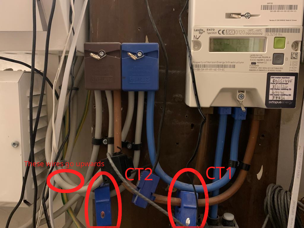
Here is the position of the CT clamps from the emonpi
The labelled wires appear to go up to a mini consumer unit
Here is the situation above:
I hope that give some idea of what’s going on  Let me know if any more detail is needed…
I need an overall view from further back, so that I can relate those details to everything else.
I think I can just see you supply fuse, I think the L&G E470 is your main meter.
Looking at the two “Henley Blocks” (so called from the original manufacturer - the pair of brown and blue terminal blocks), the input to those is the brown and blue wires from the meter. One pair of grey wires (one from each block) will go to your main consumer unit, what I need to know is which those are (left or middle) and where the other pair go.
Where is the “mini consumer unit”? Is it the white box with two glands on the top, labelled “Danson”?What does it do - is anything labelled on it, and if you lift the flap/open up the cover?
What I really need to identify is the cables that come directly from your P.V. Inverter, and where the cables to the Sunamp heat store join in. (is that what you are calling “diverter” on the photo?) So what is underneath the small white box to the right of the Danson box? I think I can see something coming out of the bottom.
The white cable you labelled “Appears to go up to the loft” - is that where your Inverter is? Where does the bottom end of it go - it looks to go through the wall, where to?
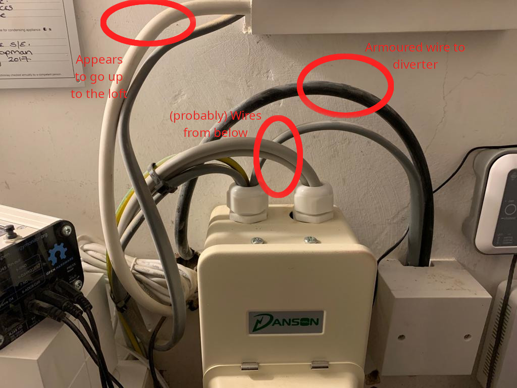
Hi again. Here’s a picture of the whole mess arrangement, with some hopefully accurate annotations:
I neglected to mention, there’s also a “Voltage Optimisation Unit” - that our solar installers flogged us - in the mix. Not sure how much use that is overall. From the Henley Blocks, the grey wires 1st and 3rd from the left appear to go to this device. I think wires then emerge from this and join to the main consumer unit.
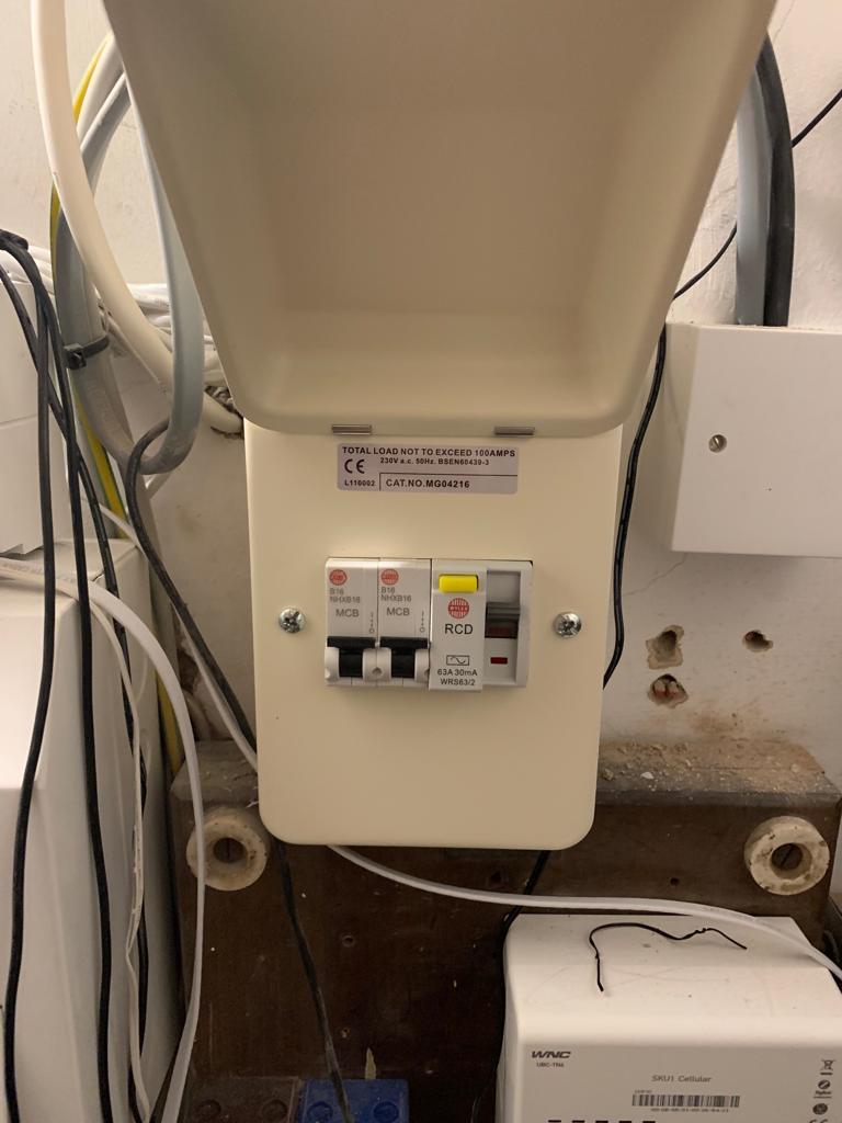
The grey wires 2nd and 4th from the left appear to go up to the Danson box. Here is a picture of under the cover:
No handy labels there, it seems…
The cable that comes from the inverter appears to be the white cable going into underneath the generation meter, where another grey cable emerges and goes into the top of the Danson unit.
The cable to the Sunamp heat store again comes through the wall and the white box does a similar job of converting to an “indoor” cable and going into the top of the Danson box.
Is that any clearer? Obviously more detailed photos can be supplied if needed. And many thanks for your time so far
I fear you were most probably taken for a ride there. Without knowing exactly what is inside and how it is supposed to work… It might even be costing you money and providing no advantage at all.
OK, I think I’ve got it now.
Actually, seeing 2 × 16 A breakers in there was a big enough clue. One isolates the inverter, the other the Sunamp. Which is which (and it’s worth finding out and labelling them) you’ll have to find out by turning one off, leaving one on and seeing which is still working, or by opening it up and looking.
You need to get at a single core of that white cable from the Inverter, or the flat grey one coming out of the generation meter and into the Danson mini consumer unit. Where I would do it is inside there - where you’ll find a single brown core going into the top of one of those MCB’s - with both the the MCBs off (down) it will be safe to go in and clip CT2 onto that wire. (You would need a tool to touch any live metal.) But from what you’ve written, I think you wouldn’t be happy messing about in there. I suspect you need to get a local electrician to do it for you.
I finally got round to getting my electrician friend to have a look. He said that he would not recommend putting the CT clamp inside the Danson unit, though it seems that is where it needs to go (onto a live core inside there). Is this the only solution? Is it actually safe, despite what the electrician says…?
I wouldn’t recommend it either, but that doesn’t mean it’s not safe, and I think it’s the best option available to you. Provided that the output lead is physically separated from the power wiring, then I would have no worries about safety. The c.t. itself is rated to mains voltage, and it’s on an insulated conductor in any case.
If needs be, remind him that BS7671 also says that installations which offer at least the same level of safety as the standard specifies are also acceptable.