I’m currently using 10k voltage divider resistors. I see it says 470k down to 10k values are good.
If I’m going to be using Arduino Megas with 15x inputs (+1 for voltage reading), does that give me reason to go with a higher resistance? Or is it pretty much something I shouldn’t worry about?
If you’re not worried about current consumption, then your 10 kΩ resistors will be fine. The point about the 470 kΩ resistors is power drain when running off battery power.
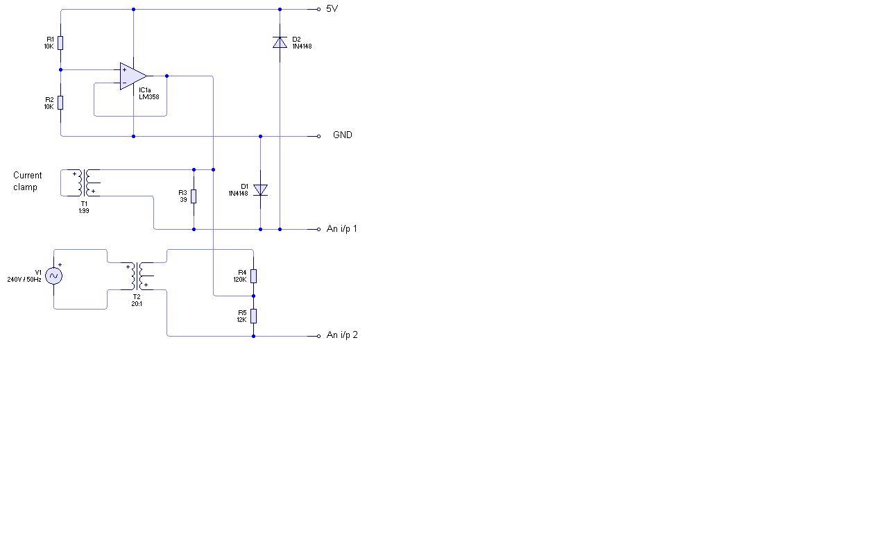
If you’re building a 15-input custom board, you might like to consider using the op-amp buffered bias supply - that is where an op-amp in voltage follower configuration follows the resistive divider, and all the inputs then use the common bias supply from the op-amp output. https://learn.openenergymonitor.org/electricity-monitoring/voltage-sensing/acac-buffered-voltage-bias
#1
Ok, I noticed no mention of +/- from the AC/AC adapter, so I figured something was wrong. But then I tested the output on my Jameco AC/AC adapter, and it returned +10V regardless of which way I tried. Apparently there’s no polarity when an AC/AC adapter is in play. Is that true?
#2
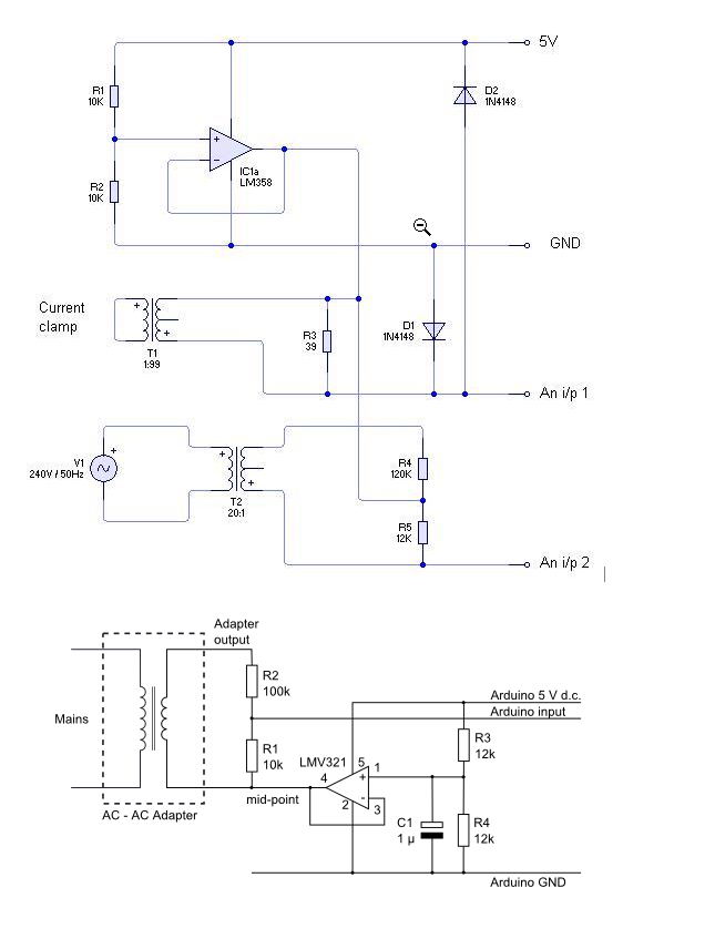
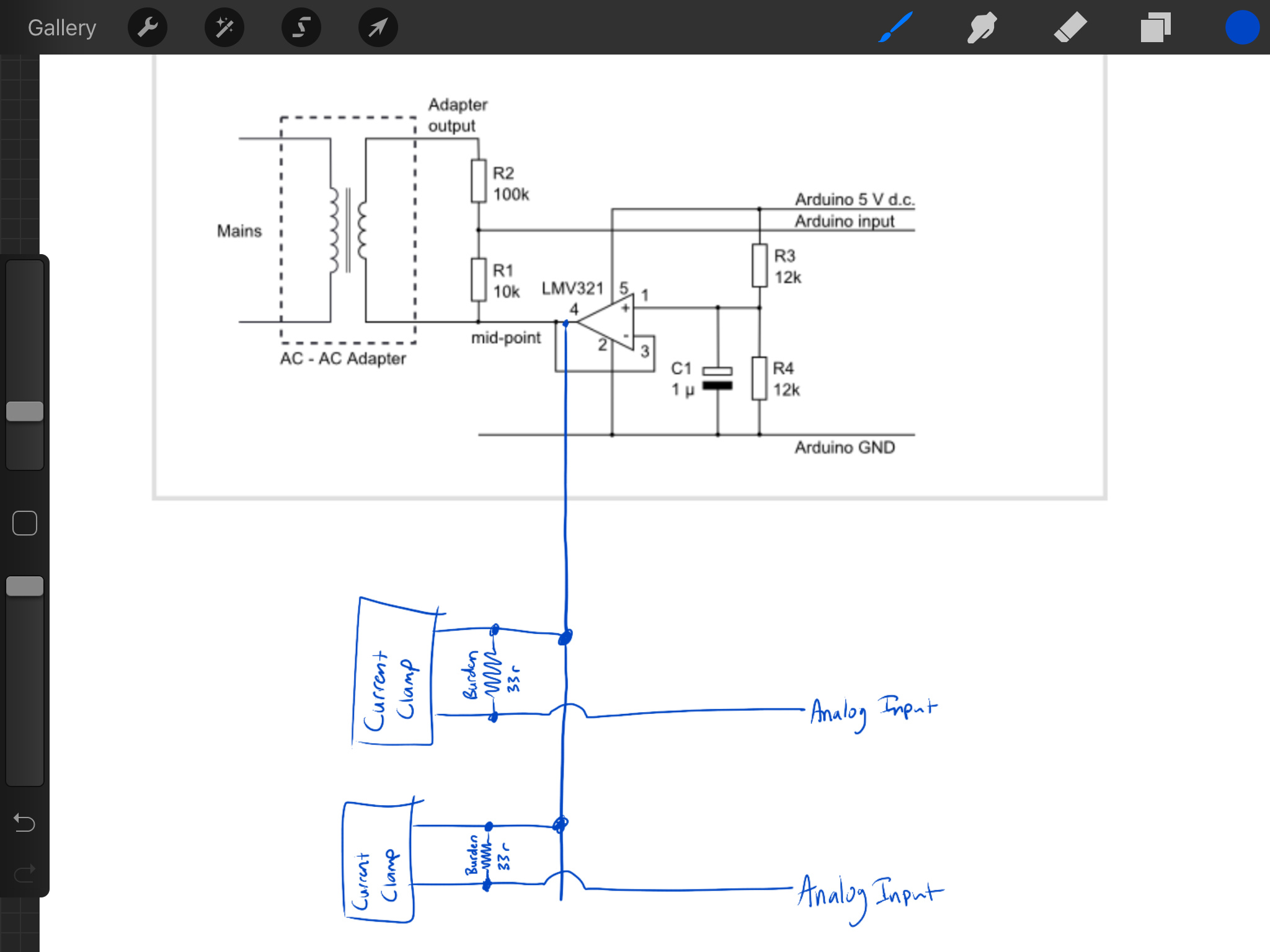
To clarify, I need 1x of these op. amp circuits per Arduino, hooked up to the AC/AC. Then, each currrent clamp hooks up to #4 on this diagram?
In this other diagram, showing a current clamp, it appears that no voltage dividers are then needed on the current clamps. Only the burden resistor. Is that so?
#3
I did not expect these numbers to be so big. Apparently Markdown styling is being used. Cool!
A.C. means Alternating Current. The polarity swings from positive to negative 60 times per second (in your case). I think your meter is wrong (as in ‘misleading’, not ‘faulty’ nor ‘inaccurate’) by showing **+**10 V, most meters when set to read alternating voltage or current show “10 V” - with no sign - in acknowledgement of the alternating value of the voltage.
But there is the slight matter of phase. Read about the importance of that in the Learn section introduction to A.C. Power Theory.
That’s correct - 1 op.amp feeds all 15 inputs from pin 4 of the op.amp (“mid-point”). That replaces the 2 resistors and one capacitor that you would otherwise have for each individual input.
There is of course no voltage divider when you have a burden resistor for your current transformer - you choose the value of the burden to give the correct voltage in the first place. (That diagram isn’t ours, incidentally. The reliable source of data is either the Learn section or the actual manufacturing schematic diagrams on GitHub.)
True, it doesn’t show +10. It only shows 10v, so I assumed + since there was no -. Good point about AC. I’m pretty sure though, with AC, if I hook it directly to the socket, -120v is when the black is on the neutral, and 120v is when the black is on the hot.
US here.
Anyway… thanks for the clarification in #2 as well. That’s great… .except for the PCB boards I ordered that have spots for each to have its own voltage dividers…
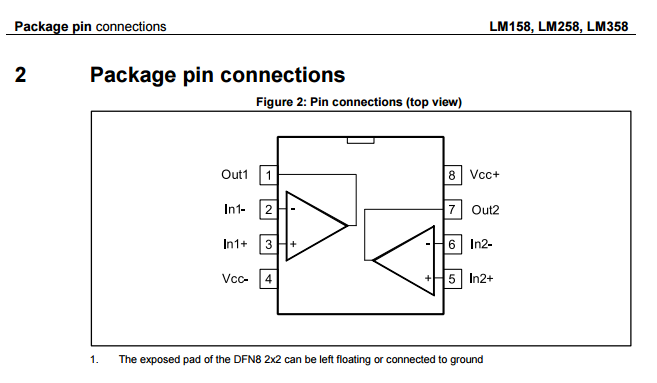
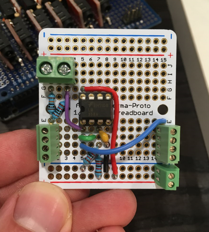
Alright, I ordered some LMV321RILTs and LM358ADTs from Digikey, and they arrived.
I’m not good enough to solder the 321’s and they don’t line up with any pads. The 358 aligns perfect.
There are more pins than I expected. Based on the diagrams linked earlier in this thread, I’m assuming that I’ll only be using pins 1, 2, and 3…correct? (In +, In -, Out)
Yes you do. They are the power connections for the op-amp to do it’s job. The in-, in+ and out are what it uses to do its job.
Both are “accurate”, the important thing is that the AC:AC input is connected across the 2 resisters in series and that the smaller of those 2 resistors sits between the mid-rail and the ADC input, which both do. Both have pro’s and con’s but the latter is the way it’s done on the emonTx v3, to permit the AC:AC input to also be used for powering the device.
The analogy is measuring 2" using a 12" ruler: It’s the same whether you measure from 0 - 2 or from 10 - 12, and both ways you get one sixth of the length of the ruler.
As long as you common them up all the same, and they all use the same d.c. supply (so that the ground reference is the same and so are the supply voltages), then that should be no problem. The voltage monitor takes effectively zero power from the adapter, so you can have an almost unlimited number.
This is not the case for the emonTx V3 unless you are using the 5 V d.c. USB connector to supply the operating power.
Ok. I plan on powering all 3 Megas directly to the 5V rail from a single 5V (10A max) supply. So, from what I understand, I need to set up 3 op amp circuits, all reading the same AC/AC.
Three op-amps are not necessary - just use one and feed the “Arduino input” to all three for the a.c. voltage, and you can likewise feed the ‘mid-point’ bias supply to all your c.t’s.
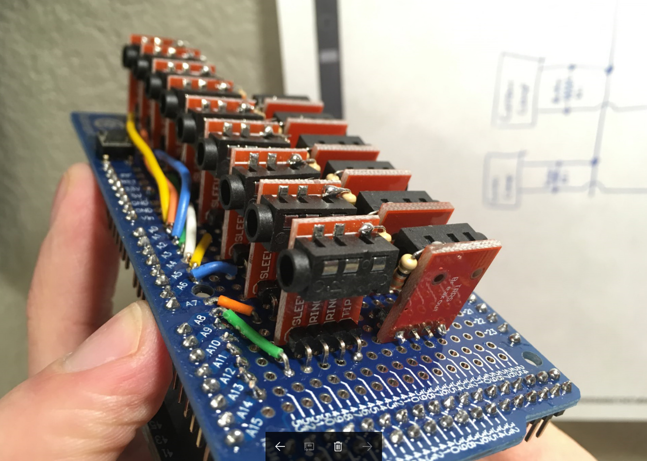
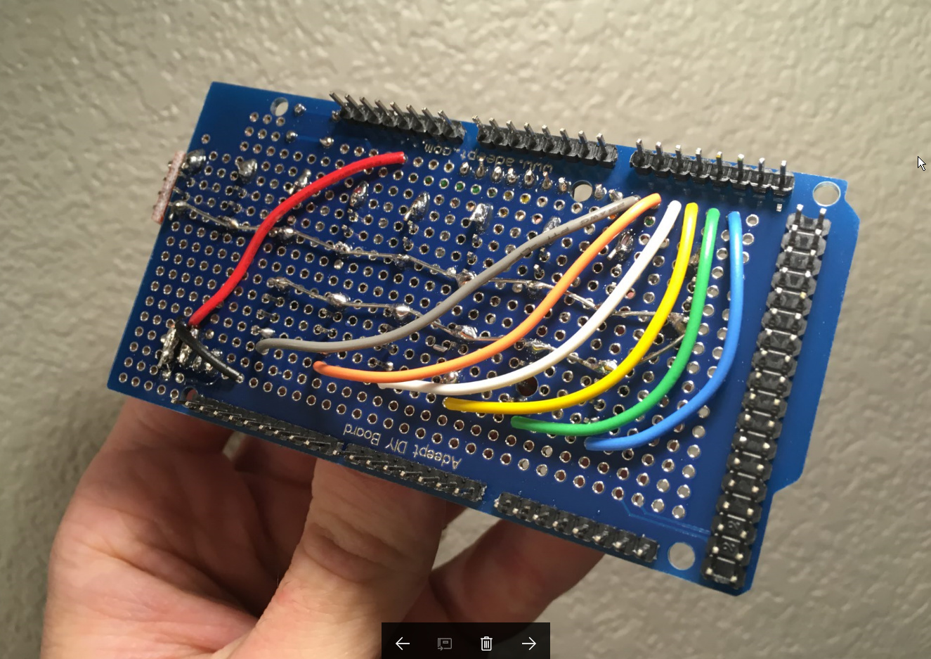
Thanks for the guidance. Here’s an update to show that your keystrokes have not been wasted.
Since I’m trying to fit 1 Pi, 3 Arduinos, a network switch, and power components into a single box, this op-amp setup has saved tons of space. I’m able to fit 15 sensor jacks directly on top of each Arduino, and the shared op-amp circuitry is contained on one single 1/4 perma-proto.
Anyway, here is the current progress.
I’m crossing my fingers hoping that there won’t be interference with those wires running so close together.
