I know the emonpi1/tx3 is not compatible out of the box with voltage CTs… bear with me.
I’m trying to figure out if I could improve accuracy of a emontx3/pi1 on lower currents using a voltage CT. For example my heatpump has 32A max supplies which could be more accurately (?) monitored with a lower rated CT rather than the blue YHDC 100A:50ma one. Typically the heatpump pulls a 20-60W or so on idle and anywhere unto 5Kw on full load.
What would need to be changed to make voltage CTs compatible (hardware & software wise) and would it be worth it ? Would the burden resistor need removed or replaced ? How big would the s/w changes be (assuming I can hack together my own firmware if I was told what needed changing) ? Or should I just shut up and spend a few hundred quid on emontx5, emon VS + new CTs (I don’t think I’ll be doing that to improve my accuracy, hence the ask)
I guess @Robert.Wall will soon point me in the right direction or tell me if its a waste of time.
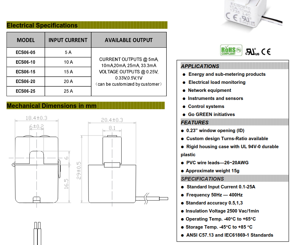
We decided to standardise on 333mV voltage output CT sensors for the new hardware as that’s the more common standard, giving us a wider range of CT sensors to choose from. This isnt so suitable for the emonPi1/Tx3, where you really want ~1.6V peak across the internal burden resistor at max current. See emonTx3 calcs here Technical — OpenEnergyMonitor 0.0.1 documentation
The emonPi1/Tx3 uses YHDC 50mA @ 100A, 2000 turn CT’s.
The ECHUN-ELC CT sensors that we use have a 33.3mA current output version but the datasheet accuracy figures seem to suggest that the accuracy falls to 3% (same as the YHDC) at the wider values, while they are down at 0.5% for 0.33V.
Thank you both… very useful information, that solves my problem, but increases my curiosity…
If i’m understanding the voltage CT doesn’t generate enough voltage at max current (333mv) , Tristan says we need 1.6V (which is higher than the adc range ?)
It begs the question, how is it done on the devices that support voltage CTs, how is the 333mv scaled up for the ADC , or is it not ?
Sorry my understanding of AVR A/D conversion is a tad limited… I know the basics but that’s it.
What’s the p.f. of your heat pump when it’s pulling 5 kW (not Kw)? If it’s 0.87 or better, that’s under 25 A and so the 25 A c.t. will be OK. (Assuming it is 5 kW @ 230 V, if it’s spec’d at 240 V, so much the better.)
The emonTx3/Pi1 has a supply voltage of 3.3V and a mid-rail voltage at half that 1.65V. The ADC range on the emonTx3/Pi1 is also 0-3.3V and so you really want to make the maximum use of that if you can, hence aiming for ~1.6V at peak current (1.1V RMS).
The emonTx5/emonPi2 has a supply voltage of 3.3V but has an analog reference of 1.024V, the mid rail voltage is close to half that and so 333mV voltage output CT sensors fit quite nicely.
I’ll have to try to figure out how to get that data.
My supply voltage is around 249V (measured by a Socomec Diris A40 on the utility), not sure what the PF is when heatpump running. With careful timing I think I can get the Diris to tell me (the HP is fed from phase 2 which has little else on it, I just need to make sure solar isn’t running and the car not charging when I look at the PF). I don’t trust the Diris accuracy to read the current/kW at the the moment as it’s on a 250/5A CTs (which I’m setting to change to a more appropriate 80/5A one).
`The emontx3 is inside the HP itself so getting serial access not trivial (assuming it can tell me the PF, it’s running CM firmware, your original release).
Thanks @Robert.Wall , I couldn’t find the 40A RS Pro CT as it’s a Talema one … The Talema 50/25A prices are different too.
Another (!) ADC explanation
In both the emonTx4 and the emonTx3 the ADC input is DC biased to half its reference voltage. The CTs are then effectively AC coupled to the biassed input. In the emonTx3 there is a burden resistor in parallel with the CT.
Edit: In the emonTx4 using the voltage CT, the burden resistor is inside the CT.
The ADC in the emonTx4 has a reference voltage of 1.024V and so measures from 0V-1.024V. So the input sine wave from the CT must be less than 1.024V peak to peak. A 333mV voltage CT gives:
0.333V RMS x 2 x sqrt(2) = 0.941V peak to peak
The ADC in the emonTx3 has a reference voltage of 3.3V and so measures from 0V-3.3V. So the input sine wave from the CT must be less than 3.3V peak to peak. A 50mA CT with the emonTx3 burden resistor of 22 ohms gives:
.05A RMS x 22 ohms x 2 x sqrt(2) = 3.111V peak to peak
The corollary is:
In the voltage output c.t, there is a burden resistor in parallel with the c.t. winding, but it’s inside the casing of the c.t.
Note: When you use a conventional current-output c.t. with an instrument that measures current directly (say a 5 A moving iron ammeter) the ammeter is the burden.