Where are you located?
Which board type do you need?
I have working V4.40 in my system and want to change to 1.9f soon.
Have the 1,9f already but only one assembled for test.
Oh I see. You need the ESP32 controller board.
I only have one and this is working with can.
Sorry.
Did you first try out only Victron GX to ESP32 CAN?
Without any other nonsense?
I had the issue thad I had to change low and high vice versa.
I suppose there is a failure in Stuart s video.
the config.txt above looks OK (again stressing that your Waveshare is indeed with a 12MHz crystal and not an 8!) easy to edit the oscillator value above to 8000000 and see after a reboot if anything changes.
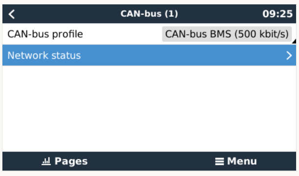
I assume you HAVE put a blob of solder on JP1 on the Controller to enable termination, right?
and don’t remember if there was a jumper or something on the waveshare that needed to be activated.
It is a 12mhz.
Yes, JP1 has a blop of solder, an measures 60phm between Hi and Lo.
Hmm, have not seen anything in the waveshare manual. Going to check that.
Just a note, I do own a waveshare (CAN / RS485 combo), and I’m the one that tested and wrote the victron wiki piece on it, BUT I’m using it for my NMEA2000 comms to Victron (for signalK purposes)
I’m using an external usb PEAK device for the canbus. Don’t remember if over xmas I’ve test used it, might have. I bet it’s something simple in the wiring or board settings.
120 Ω between hi and lo on my test board here at home (not connected anywhere) which is what the terminator resistor is onboard. Is this value taken with cables on hi and lo?
should be, worth disconnecting waveshare and testing it as well, but looks it’s OK.
odd.
You have done reboots with a different timing in firing up the controller and the rpi? ie. first the pi, later the controller, or vice versa. At some point (with earlier beta codes) I had some problems.
Other than that, I’m out of ideas I’m afraid. You do have the right can chip on the controller, right?
good point Stuart, although I’m pretty sure venusOS is happy to read as many such sections, every time I reinstall/upgrade there are such sections and things seem to work till the time I bother to connect and check…
result!
you do have to reboot the lot everytime you change something (imho)
try different on off procedures to make sure it’s going to work after an unexpected reboot/restart.
Well, either Stuarts Video has a failure or the boards lettering.
I have finally got one board to work in the way, stuart connected it in the video.
Pin 8 to Hi and Pin 7 to Low which is in fact Hi to Low and Low to Hi… as per the Canbus manual from Victron.
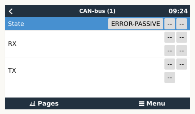
@vas it seems like, that the two not working boards have 0.7 Ohm between the 5V Port GND and the GND of the Can Port. While the other Board has OL (open line)
Hello Vassilis. My name is Detlev and I live in Germany (Speyer). You got the DIYBMS running on the Raspberry with Venus OS. Could you tell me the steps and the materials once. Gladly also to my email: [email protected]
Greetings Detlev
I’d rather reply here so:
A. others can read later on and solve similar issues
B. other forum members can also help. I don’t consider myself an expert on the topic by any stretch of imagination!
I’m using a raspberry pi HAT AND an PEAK USB canbus. One is running the NMEA2000 comms to the victron the other is running the diyBMS comms to the victron.
Either should work.
Cheapest HAT I could find at the time was the WAVESHARE one. The PEAK ones I had bought 15yrs ago believe it or not and were never used…