Did not help, still dead…
Did you manufacture your own RJ45 cable?
Check you took the right pins.
Measure the cable from RJ45 to open cable end.
I had ones an issue when I built a network cable.
The claw did not penetrate the cable in the plug.
So: no contact.
Its tricky to measure. And you have to disconnect the calbe at the controller.
Otherwise you cant measure anything.
Someone might be able to correct me on this but you might he about to sniff the canbus via serial using putty. Port 115200.
Youll have to connect via micro usb to do that. Dont forget to disconnect your 5v powering your controller.
Contacts are ok, i tooked a pre manufactured one
So, if you are sure the CAN BUS Chip is ok, everything else works.
I would take a heat gun and solder all contacts again…
Did you ever had bad soldering from JLC?
I suppose: yes…
I soldered 2 diffrend boards today.
Worked thereafter.
But I can not confirm if this was caused by jlc or by me.
1 Like
@CzarofAK
care to post a few pics from the VenusOS settings screens?
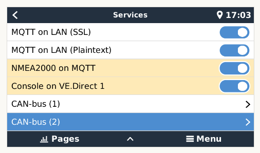
mine is in can2 as can1 is the NMEA2000 can connection, yours may be can1 (or 0 depends on version of VenusOS I guess). so settings/services looks like that:
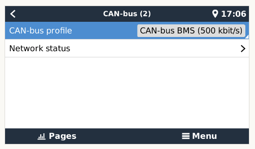
can2 looks like this:
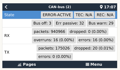
and then network status:
how’s yours?
V.
Hello Vas, sadly i have no access at the moment, as the camper is in the garage.
I use a Cerbo GX, not a raspberry.
I tried both, the BMS-Can ports (both) and the VE-Can ports (both)
I will send pictures asap
I have ordered now a CAN Hat for a raspberry. So i can check if i might have a issue with the cerbo.
Sadly i was not able yet to make a screen shot.
First of all, i use a Cerbo GX.
Pic1:
-Mqtt, NMEA2000 and Console on xy, are disabled
Pic2:
-BMS-Can and VE-Can are on BMS 500kbit/s
(Tried both ports, all variants)
Pic3:
-the BMS-Can looks different, but i have got no Receive, only transmitt
-on the VR-Can, it looks the same but only errors
I have two questions.
- i have got now a CAN-HAT (waveshare, 1 Port) for my test raspberry. this operates on 3.3V. Did you leave the diybms controller on 5V standard?
- as i noticed, that there are victron devices which are NOT 5V tolerant, did i kill the Cerbo GX now if i left the controller on 5V?
also have waveshare, didn’t change anything on diyBMS standard 5V
1 Like
how did you wire it? Hi on Hi and Low on Low? GND?
lol, don’t remember, nothing to burn if you go hi to low and vice versa, so chose the one that works. Not on the boat right now so difficult to figure out.
you NEED ground!
you DONT connect V+ at all!
just hi/low/GND
500kbps or whatever on the venus OS interface, NOT 250!
Yes, this is how a CAN network is supposed to be wired and it should work fine. As @vas notes, do not connect the V+ pin as that is not necessary for diyBMS usage.
Potentially the CAN transceiver can be damaged by incorrect wiring.
Hi @vas, @atanisoft
So, this is my setup now.
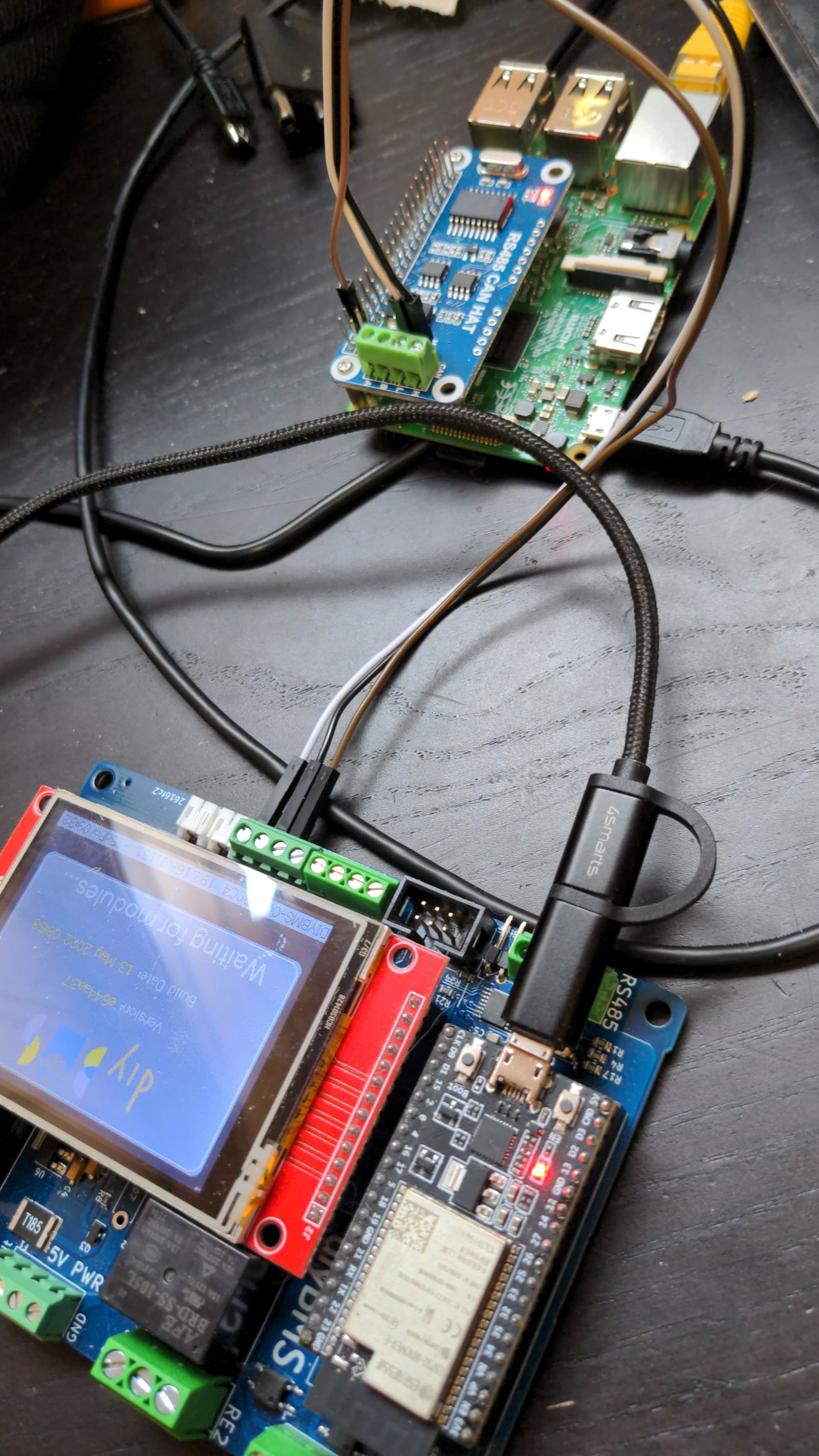
I have setup can0 and 1 to option 9 (12mhz)
Both show up as “ERROR-PASSIVE”…
it is so frustrating at the minute.
i guess i give up on the 2 boards of the first batch and the 5 boards on the second batch, and just order new ones…
does anybody order new controllerboards soon? or has at least to controllerboards left over for sales, WHICH ARE PROVED WORKING WITH A CERBO GX?
I understand your frustration.
Do you want me to send you my venus rpi image and see if that works?
That would be great
give us some more details, AND screen captures (like the ones I posted earlier) from the venusOS screens.
also a closeup pic of the waveshare board making sure it is a 12MHz crystal and not an 8MHz!
also post the config.txt of the venusOS!
ERROR-PASSIVE means it works (in older versions of the OS) what VenusOS version are you using?
1 Like