I’ve bought an emonTX an a RFM69pi that I’ve plugged in a pi zero W. Everything works fine at very close range but signal range is abysmal otherwise: I only get garbage on the pi’s serial port past ~8 meters with clear line of sight and no interference.
I’ve read pretty much all the forum’s posts related to signal range - but what I’m seeing is strange so I thought I’d ask before messing up with antennas and extending wires:
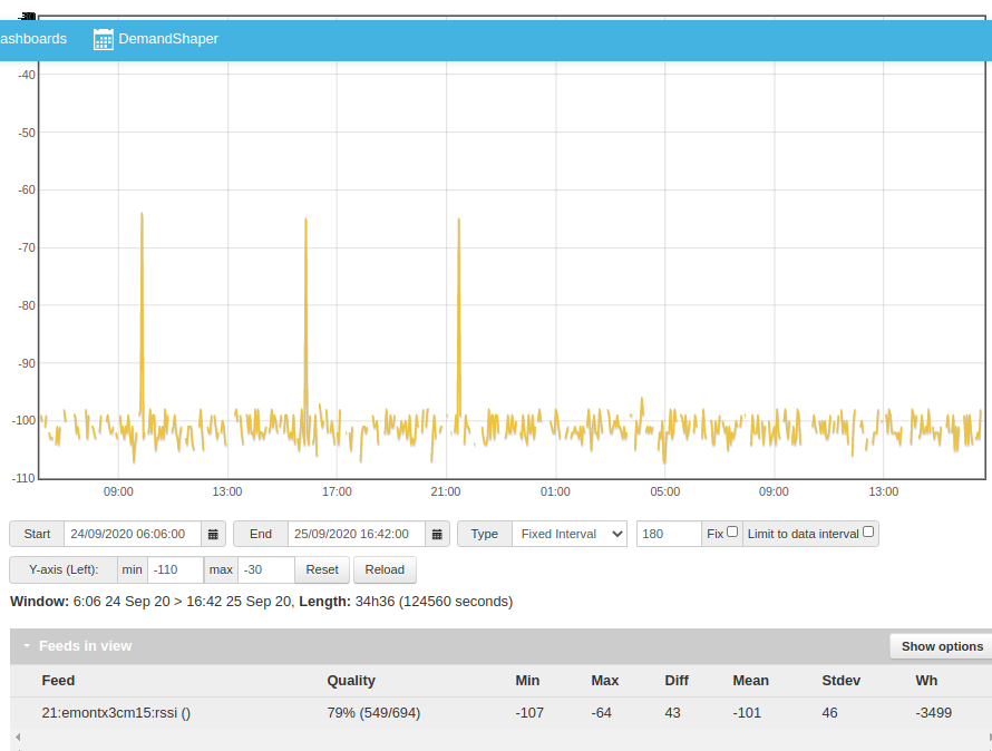
at close range, the strength of the received signal is ~ -60dB; at 5-6m it’s ~ -64dB (which is pretty good). But just a bit farther, eg. ~8m, with devices still within line of sight, there aren’t any valid packet received.
I’m in a countryside area with no known UHF devices around so interference/noise should be at a minimum. I’ve done tests at three different locations and still get the same results (in one location close to a long metal hangar the max. range is only 4-5 meters)
in all 3 locations, wifi from the pi to a laptop works very well at significantly longer distances
both devices’ antennas aren’t loose, aren’t covered by anything, are perfectly vertical, are in the same plane, etc.
putting ground planes below the devices or at the base of the antennas doesn’t help at all, with no noticeable improvement in RSSI.
FWIW the RFM board is a few centimeters away from the pi zero, on a custom made extension board also used for gpios/inputs and a RTC (but there’s nothing I could think of that could create interference).
tested with two good quality power supplies and with my laptop; same problem.
Like most radio stuff I’d have expected to see a decrease of RSSI and number of valid packets the farther the devices are apart but in this case it’s either “every packet sent by the emonTX is received” (confirmed by looking at the TX led while monitoring the serial’s port output) or “no packet is received at all”. Some forum posts mention RSSIs in the -70dB range (even up to -80dB) while still being able to receive valid packets - even through brick walls - so I’m a bit puzzled. Any clue ?
Side questions:
in case I transform the RFM’s antenna into a dipole (and/or solder a small length of 50ohm coax cable to go through a wall), what location on the RFM’s pcb would be adequate to solder the ground ? I’m concerned about soldering next to tiny smd components as my soldering skills aren’t very good…
rather than extend the emonTX’s antenna I’ll probably extend the CT cables by 2 to 3 meters with 2x1mm2 (AWG17) cables; out of curiosity, is there any maximum length (with decent cables) ?
You have a consistent operating frequency, i.e. the radio in the emonTx, the frequency it’s working on, the antenna, the RFM69Pi’s radio, its frequency and its antenna are all consistent? (probably 433 MHz)
You’ve thought of car alarm, radio doorbell, wireless burglar alarm? - not that those operate continuously, unless you have a faulty one.
Electric fences?
Both ends in different locations?
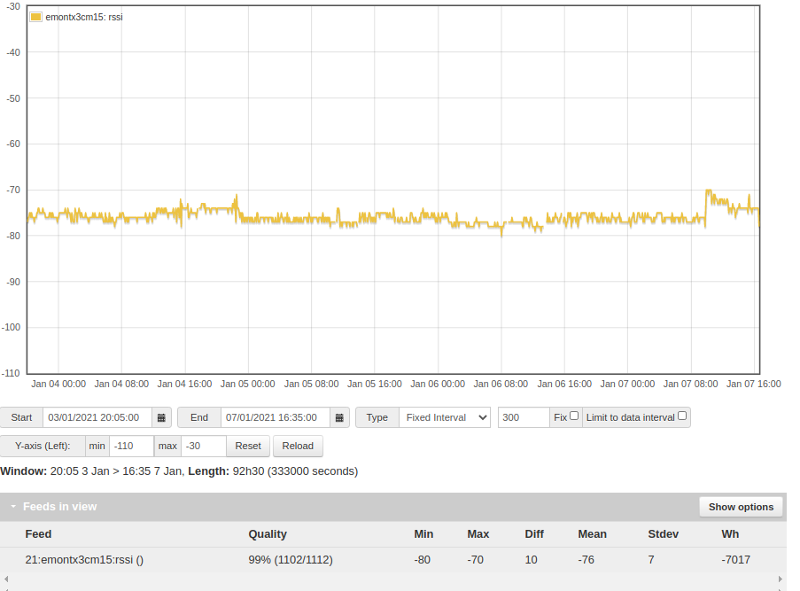
I can confirm that. This is the lowest RSSI I’ve recorded recently - through 3 brick walls and 7-8 m.
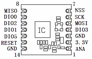
The next pad to the antenna (1) is 3.3 V (2), the one after that is GND (3). I’d use that one, but the pad immediately opposite the antenna is also GND (14).
The recommended way is described in a page in ‘Learn’. 8 m shouldn’t be a problem, if that’s the distance you need. The important part of the cable make-up is twisting the cores, so that any noise or other spurious signal pick-up is self-cancelling.
If Wi-Fi in the location of your emonTx isn’t a problem, why not connect the Pi Zero W serially and just use the Wi-Fi?
I haven’t changed any factory settings, I’m just using the devices as I’ve received them. I’m sure it’s 433Mhz in the RFM but haven’t plugged the emonTx device to a serial port so can’t say for sure. I haven’t tweaked any of the antennas.
No such modern things around Except for a radio/TV retransmitter on top of a mountain 20km away, the only nearby radio emitter at 2 of the locations where I’ve tested that setup was an off-the-shelf indoor WiFi AP. There’s no radio equipment at all at the 3rd location - a sheep farm, where those devices would ultimately be installed - and the closest neighbour is 3km away (and they aren’t hams). There aren’t electric fences either.
(Not sure I understand your question) ; both devices are at the same location, a few meters away, with clear LoS.
Which is why this really puzzles me ! I’m really curious about what could hamper reception before trying to improve the antennas. Except bad SNR I really don’t see what could cause the RFM module board from perfectly receive packets with a very good RSSI and then all of a sudden stopping receiving any valid packets when moved a few meters farther. Without nearby emitters/interference, I don’t see what could cause a low SNR in my environment - and even then, given that you seem to have a working setup at almost -80dB RSSI I should at least get 10m reception with clear LoS.
Thanks for the RFM’s pinout. The ground pin next to 3V3 looks really tiny on the board, I hope I won’t fry something when soldering a piece of coaxial cable there.
(Thanks too for the pointer to the CT cable extension page, I had totally overlooked it).
There isn’t any IT equipment at the farm - so no wireless and no internet. The Pi Zero is configured to log the status of 10 GPIOs (milk tank status, milk tank, vacuum pump and what have you) so the best location is close to that equipment in the milking room. The emonTX device would be in the farm’s main electrical DB approx. 8m away. Unfortunately there’s no easy way to pull cables between the milking room and the main DB so a direct serial connection isn’t really possible. FWIW the Pi Zero W will be configured as a standalone AP that I’ll use to download statistics every few days with my laptop.
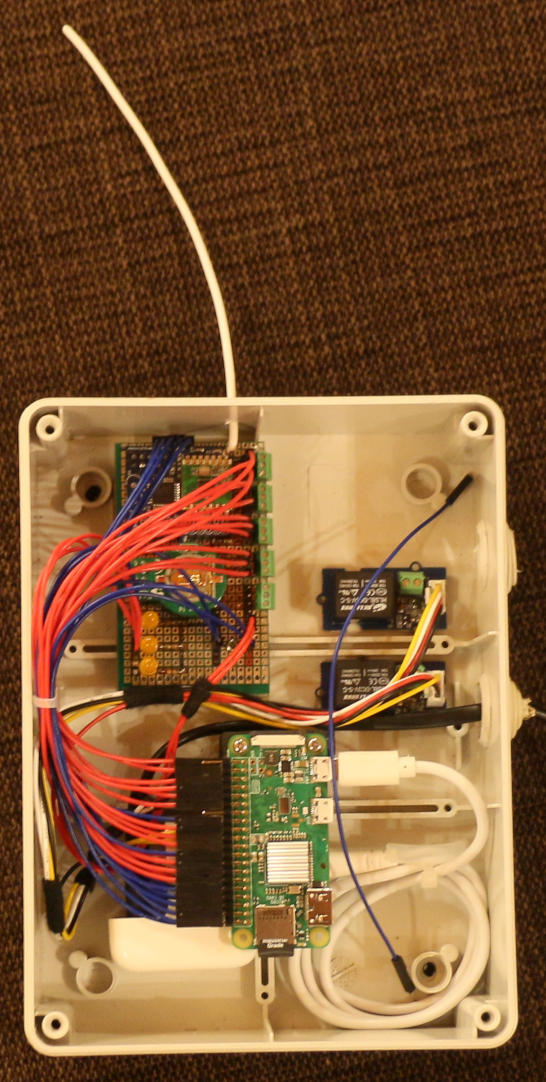
[EDIT: added a picture of the Pi Zero W with the custom board]
the custom extension board is pretty basic, with a few status LEDs (to GPIOs), two 2x5 headers for the RFM and a Pi RTC (the roundish thing below the RFM), and terminal blocks (to GPIOs) to wire relays from the milking equipment.
the box is plastic (probably ABS).
the power supply is from a good quality smartphone. I thought it could be generating interferences but the same thing happens with other PSUs plugged 1m away.
one thing differing from pictures seen in other posts is that I’ve put the RFM’s antenna in the same plane as the PCB - not perpendicular
the two other small boards on the upper right are relays for buzzers. They were not energized during the tests.
(I see I forgot to remove a spare blue wire from the box before taking a picture )
It was worth asking. If everything came from our shop, it should be all correct.
What I was getting at was, are there reflecting surfaces that could give you a deep null at either end of the signal path? Even so, given the wavelength involved, you’d need to be quite precise to find a null - a few 10s of millimetres would move out of it.
It’s totally puzzled me too. @Bill.Thomson is the radio expert here - I see he’s about to contribute. Maybe he’s got some ideas.
which is why I asked about moving things around.
That scuppers that idea then.
Have you tried plugging the RFM69Pi board directly onto the GPIO of the Pi, rather than using those rather long leads and the prototype board? Is there local decoupling on the power supply to the RFM69Pi?
That I would expect to affect the RSSI proportionally, not cause it to fall over a cliff.
Very clean install. Almost sounds like a frequency mismatch between transmitter and receiver.
I say almost because the behavior is very similar, but the range with a freq mismatch is typically considerably shorter than what the OP describes.
What is the board in the upper left corner of your picture?
Is it positoned on top of the board with the RF module?
Or is it the board with the RF module?
The first thing that comes to mind is the wiring that’s running atop of the RF module.
If it’s carying digital signals, it might be an RFI source, and given the proximity to the RF module, affecting its operation.
There’s a metallic building at the farm but there’s nothing that I can think of at home (where I did most tests) that could make reflections so bad as to have such nulls. Moreover I’ve put the devices at random places when doing tests, without any improvement, so this doesn’t seem to be the issue.
I plugged the RFM69Pi on the Pi’s GPIO header to make sure it worked before moving it to the extension board but that was with both devices on my desk. I haven’t tested “long” range without the extension board, now that you mention that (good idea!) I’ll try that on this evening or tomorrow morning.
Otherwise no, there’s no decoupling on the power supply. The extension board is just that - an extension of the Pi’s header, there isn’t anything other than wires, a few leds and resistors.
Thanks
It is indeed the board with the RF module - bought from the shop (the red and blue wires give the impression that there’s another IC on the left but it’s the same board). Below that, the thing with a round form is the RTC
The red wires atop the RF module are GPIO inputs that will eventually be wired to relays actuated by the milking room’s PLC at most a few times a minute - so nothing that could be a RFI source.
On the other hand the blue wires are extensions of the first 2x5 pins of the Pi’s GPIO headers - so there’s i2C (for the RTC - but as far as I can tell it’s configured with a slow speed) and the RF module’s serial TX/RX + reset GPIO (and obviously, vcc and gnd).
I’ll definitely unplug the extension board (ouch, after all that time spent making it all clean and tidy ) and test only the RF module with the Pi and see what happens.
I would highly recommend trying what Robert suggests here
either that will improve it or it won’t. If it does, you need to look closer at your gpio breakout and wiring, or perhaps just the routing?
If there is no change I would look closer at the PSU, I have not yet experienced a phone charger that was good enough for a Pi especially when there’s an rfm device in the mix. You say
The issue may not be airbourne, maybe the PSU isn’t smooth enough so position wouldn’t play a part. And
what are you calling “good quality” ? The USB port of your laptop is unlikely to be a good power source. To rule out a PSU issue you should be trying a known good 2A+ PSU (not charger). I have a rock solid 3A charger that I always pull out for debugging, when talking about PSU there is a world of difference between “working” and “working properly”.
If the same occurs when using a known good PSU when the rfm2pi is directly connected to the Zero, then further debugging is called for and then once resolved, you can try bringing the phone charger and gpio breakout board back into the mix.
Are you able to separate the emonTx and rfm2pi in smaller steps to see any traffic between -64dB and -80dB? If you see packets in the -70’s but not the -80’s check the FW revision, I know JeeLib was changed at some point to filter out packets below -80dB, but OEM were using an older revision of JeeLib, I don’t know if that’s still the case.
Have you set quiet = false in emonhub.conf to see if there are any packets received but fail CRC checks logged to emonhub.log?
Even at slow speed, signals with a sharp risetime can generate RFI quite a way into the MHz region. Although the receiver operates at 433 MHz, an RFI source that near to the receiver could be brute forcing its way into the receiver’s front end or desensing it somewhat. Admittedly a long shot with either
one, but still a possibilty.
(thank you again all for your prompt replies and pieces of advice; it’s much appreciated)
So:
switching PSUs with a “real”, high amp one didn’t help
however, plugging the rf module directly in the Pi was a huge improvement, I can now see valid packets at -64dB at a location where no valid packets were received before.
I’ve put back the breakout board with nothing else plugged other than the rf module and the signal is still good.
I’ll continue debugging this tomorrow, adding components on the breakout board one by one until I find the culprit and I’ll post back here (I suspect that i2c’s clock wire will be the issue as @Bill.Thomson mentioned - I don’t see what else could lead to RFI on the breakout board).
Well, I’m afraid I won’t be able to debug this further
After yesterday’s discussion about interferences I thought it would be useful to have an external antenna I could move in case the farm’s metallic structure nearby ended up being problematic (the box with the RF module has to be anchored at a specific location without much room to move it around). Alas, despite taking extra care when soldering a tiny coaxial cable with a SMA connector to the RF module, for some reason gnd and 3v3 are now shorted. I don’t see anything wrong with the soldered pins (no solder splatter, no visible short circuit, …). The only component close to the soldered pins is capacitor C4, maybe it’s fried and now acts as a short circuit, although I don’t see why as I paid extra attention not to heat too much with the soldering iron. I’ll try to remove the capacitor this evening to check if it’s the problem but after all the time I’ve spent on the RF side of the project I’m a bit upset (at myself) - I’m not very handy at soldering tiny stuff so I’ll probably make things worse. I’ll probably order a WiFi module for the emonTX device and call it quits…
C4 is local decoupling for the 3.3 V VCC supply. In the circumstances, it’s worth trying to unsolder it and remove it completely. Put you solreing iron bit on both ends at the same time and slide it off as the solder melts. https://wiki.openenergymonitor.org/index.php/RFM69Pi_V3
Actually gnd and 3v3 aren’t shorted - I was just about to edit my post : there’s actually ~55ohm between both pins (board unplugged). With the RF module plugged the 3v3 voltage on the Pi Zero is 0V, and 3.3V when it’s unplugged so I was dead sure it was shorted (my multimeter was also beeping the same way it does when measuring a “real” short, so I didn’t even think of looking at its display).