I have an optical pulse counter on my main electricity supply meter which feeds into my EmonPi and is working fine but I also want to count pulses on my solar generation meter which is a long way away from the EmonPi.
I use a 1-wire setup to feed data into a weather station and I have 1-wire cabling in the area where the solar generation meter is located so I am wondering if I can use a second optical pulse counter on the generation meter to feed the pulse count into my 1-wire system. I have a spare 1-wire counter module which usually counts pulses from a tipping bucket rain gauge which operates a magnetic switch every time it tips (i.e. it just makes then breaks a circuit which the counter module registers which is stored by the 1-wire software). What I need, therefore, is a signal from the pulse counter which will trigger the counter module just a make or break on every pulse - anybody any ideas?
You need to look at that and see exactly what the reed switch does. The ‘shop’ optical pulse counter emits a voltage pulse which, although it can run off a 3.3 V supply, is claimed to be “TTL”. If your reed switch pulls whatever it is connected to up to somewhere between 3.3 V and 5 V, and the same voltage is available as a power supply, then I think you should be able to connect the optical sensor output to where the reed switch is. Failing that, you need to get full details, or reverse engineer, your pulse module to find out how it works and hopefully how you can interface the two.
Unfortunately, we haven’t been able to get details of the internals of the optical sensor.
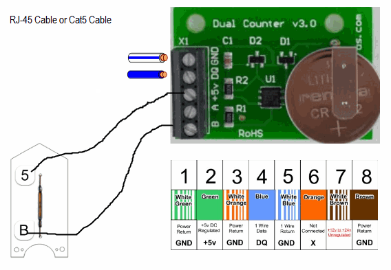
This is the 1-wire counter I use - operating the reed switch increments the counter so what I’m hoping is to use the optical pulse counter to effectively replace the reed switch. The onboard battery supplies the 5v which the reed switch connects to the terminal ‘B’ to increment the counter.
Edit - attached picture to post. BT, Moderator
It’s a guess (hopefully an educated one) that if you connect the sensor to GND, B and +5, it should work.
Thanks Robert
The three connections from the optical pulse sensor are Vcc, Gnd and TTL Data. Obviously Gnd goes to Gnd on the Counter Module but how would you suggest I connect the other two?
VCC to +5 V, TTL Data to B.
Thanks - I’ve ordered one & I’ll let you know how I get on
It works fine! Thanks Robert