Apologies if this is not the right place but I’m looking to integrate a PV diverter switch (to heat immersion heaters with an on-grid hybrid Solax E series inverter. I’m wondering if anybody else has the sort of setup I’m thinking about. The E series inverters have an emergency power supply function which I need to keep refrigerators and heating systems running when the grid goes down. The PV array is of such a size that I will still be exporting even after the battery and self consumption requirements have been satisfied so I then want to turn that energy into hot water and reduce the gas bill.
As far as I can make out there will be conflict between the CT for the inverter trying to charge the battery/maximise self consumption and the CT for immersion heater switch. If the self consumption function in the inverter notices the export before the diverter switch logic cuts in all well and good, but if the diverter switch cuts in first the inverter merely sees an increased (+3KW) load and will start to discharge the battery to help. I don’t want it to do this as it will reduce the endurance of the EPS system.
Does anybody have any experience of similar arrangements?
I can’t recollect anyone mentioning anything like your setup.
The diverter designs published here attempt to balance the nett grid current as measured by their CT to zero - presumably that is exactly the same algorithm that your inverter uses? I’d need to know a bit more about where you can measure current in relation to where the inverter connects into your system.
It’s certainly possible to insert a bias so that there has to be a nett export before the diverter starts to heat water, but it would also be worth exploring the possibility that the inverter can announce what operating mode it is in, and use the knowledge of that to influence how the diverter operates.
I actually have a similar thing set up in my home.
I have just over 6kW of solar panels, a Tesla Powerwall home battery, an electric car and an iBoost immersion heater controller. You can see the thread for my car’s charging controller here: https://openenergymonitor.org/emon/node/10805 (although it has evolved a bit since then. I’m planning an updated thread soon)
Firstly my system prioritises charging the Powerwall home battery. When that’s done, or if there is still surplus electricity, the car’s battery charges. If the car isn’t connected, or for any other reason there’s still some surplus electricity, the iBoost kicks in.
No fancy switching arrangement is required, you can do this simply using the CTs. Where the Powerwall’s CT is clipped onto the main tails, I have also run one of the conductors of the iBoost supply circuit through the same CT. This effectively adds the iBoost’s consumption to the surplus.
When the iBoost is off, this has no effect and the Powerwall charges as normal. However, if the iBoost is running, the Powerwall ramps up the charge rate and the iBoost’s own CT sees that there is no longer any surplus, and ramps down the immersion heater.
I’ve also done the same thing with the EV charge controller. It works very well.
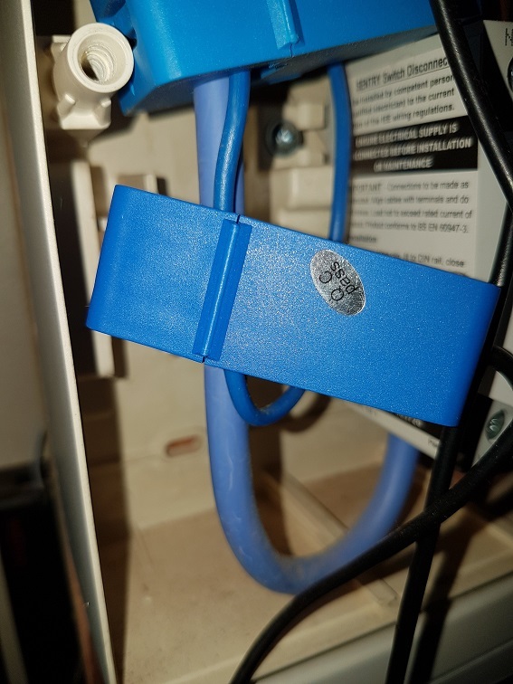
I’ve attached a photo of one of the CTs. Hopefully you will see what I mean.
Which way is the current flowing in the iBoost/EV cable? Am I right in thinking that its the opposite way to the incoming mains? That would give you a current of
(House load + iBoost+EVcharger - PV export) through the incoming mains cable
and running the supply to the iBoost and EV charger trough the auxillary cable gives
a net current through the CT of
You just need a CT with a big enough throat to handle both cables.
If you cant do that, which is probably more to do with physical limitations of space for the CT’s. then I take Roberts point of finding out what ‘mode’ the inverter is in. As the supplier seems unwilling/reluctant to answer the question I’m wondering if clamping a ‘Hall sensor’ to the battery cable would help. This could give an indication that current was flowing to/from the battery and could be used to provide an inhibit signal to the power router. I’ve already done the software on the lines of Martin Roberts and Robin Emley’s work ( it hasn’t got a box or triacs yet) I just need to think how to test a DC current inhibit off line before I buy this new inverter and battery
Ignore the fact that there are two CTs in the photo; one is connected to a monitor which has no bearing on the operation of my system.
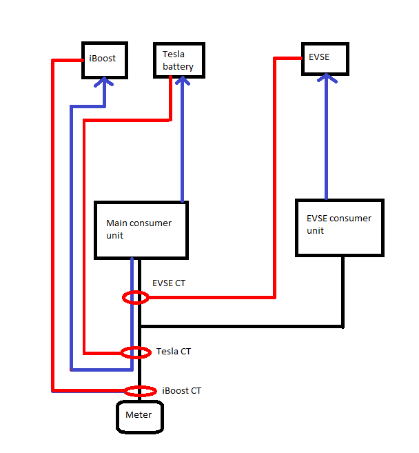
The iBoost CT clamp goes around the mains tail directly beneath the supply meter as per the manufacturer’s instructions. It therefore monitors for export in the same way as any other installation.
The Tesla’s CT clamp goes around the same mains tail and iBoost supply. This makes the iBoost’s power draw invisible to the Tesla, allowing surplus PV to be prioritised to charge the Tesla battery.
The mains tails go from the meter into Henley blocks, where they are split to supply the house consumer unit (which feeds the iBoost and the Tesla) and also a separate consumer unit for the EV charger.
The EV charger’s CT clamp is the one in the picture in my earlier post. It is connected around the main neutral conductor inside the house consumer unit and also has the iBoost supply running through it.
This means that the priority for surplus PV is ‘charge Tesla’, ‘charge EV’, then ‘use iBoost’ in that order.
I’ve attached a scruffy single-line drawing if it helps: