Using EmonLib to Measure Voltage and Current with Arduino

Hello,

I currently want to monitor AC voltage and current with an Arduino in a different fashion than the one that is discribed on the building blocks page of OpenEngergy.org. I’m building an Arduino system that will monitor voltage and current for my O scale model trains and I’m looking to get a few of my questions answered. If anyone could help, I would apprecaite it.


Voltage Reading:

On the voltage side my max voltage is 18V (RMS), so peak-to-peak would be around 31 volts (20% added on when there is no load on the system), which is possibly when no trains are running on the track.

Open Energy Reference - https://openenergymonitor.org/emon/buildingblocks/measuring-voltage-with-an-acac-power-adapter

Here are my questions related to the voltage divider:

  1. When sizing the resistors R1 and R2 shown on the building blocks page. I left the value of R1 as 10k and calculated R2 to be 300k. Is this adequate?

  2. Do I need to recalculate the values for resistors R3 and R4 for the voltage bias or can I use 470k? Based on my calculations the positive peak for the voltage bias is 3.5V and on the negative side is 1.5V.

  3. Will I be okay using a capacitor size of 1uF to 10uF for C1 or do I need to resize it?


Current Side:

On the current side my max current is 20A (RMS), so peak-to-peak would be around 29A, call it 30A. I calculated that I need two 56 ohm burden resistors in series using the spreadsheet on openenergymonitor.org.

Reference - https://openenergymonitor.org/emon/buildingblocks/ct-sensors-interface

I have the following questions:

  1. What value resistor should I use for R1 and R2 for the current voltage divider as shown in the reference link above. Will 470k due for my project?

  2. I’m okay using a 10uF capacitor or do I need a higher value?


Software:
How do I determine my calibration value for voltage and current readings and also for phase shift?


I’m sorry if these question seem trivial, but I’m new to this and I have learned so much thus far.

I appreciate any help and thank you in advance.

Chris
If you’re using an Arduino, is it running off 5 V? If so for both voltage and current inputs, you’re realistically looking at 1.6 V rms at the analogue input, after taking component tolerances into account.
So for 18 V (21.6 V off-load), a divider with resistors in the ratio 12.5:1 is required. That doesn’t fit with standard values so I’d choose 10 kΩ & 15 kΩ, giving you a max input of 1.35 V rms. Your values leave a lot of the available range unused, hence you lose resolution.
You can do much the same sums for current. If you want to read 20 A rms - with the standard 100 A CT? - then you want a burden of 160 Ω. Again, your burden seems to waste a lot of resolution.

You can keep both sets of bias resistor at 470 kΩ if you wish, or reduce the value to something like 22 kΩ . The high resistance was chosen to reduce the current for battery operation - I guess that’s not a concern for you. Keep the decoupling capacitor at 10 μF.

Given the values above, you can look at the calibration theory page in Resources > Building Blocks, and see if you get 16 for the voltage and 12.5 for the current calibration constant. Unfortunately, the phase & timing error isn’t quite as easy. I haven’t tested the CT with that value of burden, but its phase error will be slightly worse than the 120 Ω burden that I tested (see the test report). I presume you’re not using an isolating transformer with the voltage input, so the phase error will be due to the CT alone. But you still have the timing error due to voltage and current being sampled separately. I think the easiest way is to set it empirically by trial and error - rig up a pure resistance load (not a motor) and adjust PHASECAL to give as close to unity power factor as you can get. Bear in mind that the CT’s phase error is current dependent so it will only be correct at the current you used when setting it.

Robert,

Thank you for the quick reply. Yes, I’m using an Arduino on 5V. I have taken a look at the information you provided and I’m not able to reproduce your values. I’m also not sure why we are not considering the peak-to-peak voltage?


Voltage Side:

Based on what I read on the building blocks pages. The calculations are as follows:

Vrms = 18 V

Vmax = Vrms x 1.20 x Sqrt(2) = 30.55 V (This the peak-to-peak voltage with 20% added for no load) - Note that I’m unsure if the 20% is needed or not for no load, but for now I’m assuming we do.

Based on the information @ https://openenergymonitor.org/emon/buildingblocks/acac-component-tolerances

If we assume R1 = 10k where the actual value is 10.1k and the midpoint of the Arduino voltage is 2.376V.

Current @ R1 = 2.376/10.1 = 0.235 mA

Voltage Across R2 = 30.55V - 2.376V, so R2 = (30.55V - 2.376V)/0.235 mA = 120 k

Peak Voltage Input into Arduino = 30.55V x (10/(10+120)) = 2.35V

I will use a 22k resistor for the bias resistors and decoupling capacitor of 10 uF.


Current Side:

I’m going to use the 100A CT

Primary Peak Current = 20A x sqrt(2) = 28.28A, call it 29A

Secondary Peak Current = 29A / 2000 turns = 0.0145A

Ideal Burden Resistor = 2.5V / 0.0145A = 172.41 Ohms (Need 180 ohm resistor?)

Again, I will use a 22k resistor for the bias resistors and decoupling capacitor of 10 uF.


To be honest Robert I have no idea if I have an isolating transformer, I doubt it but is there a way to check? I will look at the calibration pages. Are you saying when doing the timing error, that I can’t use the train on the tracks and am better off using a resistor load to measure?

I’m not questioning you, but just curious to what I’m missing and/or doing wrong. I appreciate the help.

Chris

You didn’t say what the shape of the voltage and current waveforms is, so in the absence of that - seemingly supported by your argument - I was assuming a sine wave. I prefer to remember two ‘magic’ numbers - 1.1 V for the 3.3 V emonTx and 1.6 V for the 5 V Arduino - and work in rms values rather than convert backwards and forwards between rms, peak and peak-peak. I’d already taken the 2√2 and tolerances into account when I wrote that you are looking for 1.6 V rms at the analogue input. If you work backwards from 5 V p-p and take off tolerances for all the components (don’t forget the 5 V rail in your Arduino!), you should get a little above that. Bear in mind this is practical engineering, and there are a lot of variables not under your control, so allowing a bit of extra ‘headroom’ is never a bad thing, but you don’t want to overdo it.

Adding 20% for no-load - that depends entirely on the transformer you’re using to drop the incoming 120 V or whatever down to 18 V. 20% is probably a little pessimistic bearing in mind it’s a minimum rating of 360 VA (larger transformers tend to have better regulation - I’ve just checked a large on-line supplier and a 200 VA, 18 V one is given as 7% typical), but without knowing the details, we can’t be sure.

Oh no it isn’t - the peak voltage is 30.55, not peak-peak.

There’s a typo in my values (It was after midnight when I wrote it!), the resistors should have been 10 kΩ & 150 kΩ. (If you use a 130 kΩ for the ‘top’ one, that would be OK.) It’s obvious what I meant when I gave you the ideal divider ratio.

You want to go down with the burden resistor - going up will lower the maximum current that you can measure.

13 and 16 are valid values in the “E24” resistor series, but they might not be readily available to you, in which case you need the nearest (in the appropriate direction) “E12” value.

I don’t know the effect your controller will have on the current waveform, so calibrating the measurements with something you know will give you the correct setting, and will mean that you can trust the measurements, you won’t get any nasty surprises later.

Just one point that’s worrying me slightly - you are measuring the power before the rectifier and controller, aren’t you? The “isolating transformer” bit was about whether there’s a connection between any part of the traction supply and the rest of the Arduino and anything that’s connected to it. If you don’t have the equivalent of the ac adapter (which is an isolating transformer), then you connect your 2.5 V midpoint to the traction supply and there’s another connection somewhere, you’ve got a short circuit and anything could happen - most likely it won’t work but it could cause damage somewhere. You need to think about that and check.

Robert,

I apologize it took me a day or so to get back to you. I had somethings going on that took me away from responding.

I have added my spreadsheet for calculating the resistors and also the burden resistor spreadsheet from openenergymonitor.org on Google Drive.

The calculations yield the following:

  • 10k and 150k for R1 and R2 (voltage divider)

  • Two 82 ohm resistors for the burden resistor in the voltage diver.

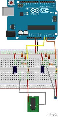
Here is my fritzing sketch:

The transformer output (18V) is producing a smooth sine wave. This input is then connected to another box which always the user to control the voltage at the track. This device takes the smooth sine and converts to a chopped sine wave, which is better for command control locomotives. The command control there is always 18V to the tracks, but older changes there speed is controlled by controlling the voltage to the track. The device that the transformer is connecting is to allow the user to just to regulate the voltage on the track. In my case I run at 18V all the time, but sometimes I operate my older “conventional engines” that require me to change the voltage from anywhere between 0V to 18V. If you are wondering what I’m talking about, here is a video from one of the train manufacturer’s here in the States that discuss what I just said, located at https://youtu.be/1Ilj3p-Ov3c

I’m going to verify this Friday or Saturday to see what the voltage is with no load. The “transformer” is taking a 120V down to 18V.

Aw…Sorry I missed the ratio. I got to wrapped up in the equations and numbers.

I guess this is something I will just have to play with to get it to work.

The transformer doesn’t generate any DC power. The trains that I have all run on AC electricity, so that means there is no rectifier. I would be measuring the chopped sine wave for the second box I mentioned, which is putting out a max of 18V @ 20 amps. do you think I still have a problem with causing a short (see my sketch above)?

Thanks,

Chris

All that gives me a much clearer picture. I quickly skimmed through that video, but I haven’t got half an hour, nor indeed the data allocation for half an hour’s worth of talking head! It’s a pity people have got into this habit of making videos when a single clear diagram would convey the essential information at a glance. Having done drives and controls for most of my working life, I think I’ve got a fair idea of what’s going on. The biggest (d.c.) motor that I dealt with was 3 MW - yes, that’s a big ‘M’.

The voltage wave will be more or less a true sine wave. It’ll be dented slightly by the current pulses, but there will have to be at least some filtering present, which will smooth things out, but probably not completely. I wouldn’t worry about getting the voltage divider correct for 18 V rather than 22 V - in the big scheme of things, that won’t make a significant difference.

It’s a bit different in the current department. As I mentioned, I expect there to be a filter somewhere downstream of the transformer and upstream of the actual power switch that does the chopping. That filter will tend to absorb energy from the supply when the switch is off, and deliver it to the loco when the switch is on, thus smoothing the current waveform. But you can’t expect it to do that perfectly. The software in emonLib is quite capable of giving you the correct values even when the waveform is distorted, as it will be.

The question of a possible short circuit remains, and your picture of an Arduino doesn’t answer it, unfortunately. If your Arduino is powered via its own power supply that has no connection to the traction supply (other than though the mains), then it’s unlikely that there will be a problem. But it’s something that can be tested quite easily: measure the voltage between the Arduino 0 V rail and the transformer output where you’re going to connect the voltage divider resistors. You may or may not read a voltage. Now connect a reasonably low value resistor - depending on the voltage you measure, it could be a 24 V light bulb, or a 1 kΩ resistor. If the voltage collapses to zero, or very nearly, there isn’t a problem. But make sure you do the test with whatever you need to calibrate and read the output connected to your Arduino.

For calibration, I’d not use the controller and (assuming you have a power resistor of the correct rating) use that directly on the 18 V transformer output and calibrate with that. But you need a fairly substantial resistor - ideally about 1 Ω, but anything up to 3 Ω would be quite good, smaller than that would be better than nothing but not ideal, and about 360 W rating for a 1 Ω one. I’m thinking in terms of several mains voltage electric heaters in parallel? (two 3 kW, 120 V heaters would do nicely, or a couple of car headlamp bulbs - the tungsten filament variety - in series).

hello all,
i am using emon library for my application to measure current.
values that i am using
CT ratio is 1:1000
Rburden =15 ohms
R1 & R2 = 10 kohms
C =10 micro farades.
caliberation value = 65

i am able to read correct values, but whenever i turned on/off the motor, it is restarting and the serial port is disconnecting.

i am not able to solve the problem, what would be the reason?

please can anyone help me?

Most likely, an inductive spike is causing a reset. A motor winding (and a transformer, and a relay) is an inductance that can store energy as a magnetic field. When you break the circuit, that magnetic field can no longer exist and the energy has to go somewhere, so it generates a high voltage across the switch (either a mechanical switch or an electronic one - they work the same way) in an attempt to keep the current flowing and it is that high voltage that is causing the trouble. You need to add a contact suppressor if it is an a.c. circuit that is being switched, or a “flywheel diode” if it is a d.c. circuit.

hello Robert Wall,

thank you for immediate reply,
i am using relays to turn off/on, and i am using AC current to run motor.
this motor operating by arduino.

as per your suggestion the contact suppressor where i need to add , means in current coil circuit or before relays.

Probably both.