Hi,
I have successfully used YHCD CT sensor of 100Amp with Arduino for measuring current up to 100Amp.
Now I am stuck with a sensor Current Transducer HASS 600-S of company LEM.
Data sheet link https://www.lem.com/sites/default/files/products_datasheets/hass_50_600-s.pdf
I need to measure current upto 600A. How can I interface it with my arduino?
From the data sheet, it appears that you can simply feed the output directly into the analogue input of an Arduino running at 5 V. You do not need the analogue input circuitry that the current transformer requires (i.e. the bias offset resistors and capacitor, nor the burden resistor). But you should include the load resistor mentioned in the data sheet.
For calibration, the calibration constant for emonLib is the current that gives an input to the ADC of 1 V. You can calculate that from the values given on the data sheet.
Thanks Robert,
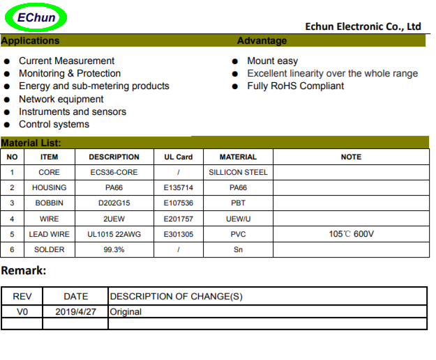
I am not sure about this CT. I have found out one more CT http://www.echun-elc.com/UploadFiles/201961118845779.pdf. This is available in my region.
Can you give any tips on this one?
That is not a current transformer, it is a current transducer. You cannot use that with emonLib to calculate real power, because the output is 4 - 20 mA d.c. and can therefore not carry the phase information necessary to do the calculations.
If you look at the page in ‘Learn’ about using the emonTx in North America, you will find many c.t’s listed that we know will be suitable, so just get one that is good to 600 A, eg Magnelab SCT-1250-000, Wattcore WC5-1000, Sentran 4LSF-600-100mA
Sorry I shared a wrong link.
I have attached the right one
Is this compatible for measuring 600A DC ?
That is not the best choice. It is a voltage output type, the maximum output voltage is 333 mV. That means you are using only one fifth of the input range of the Arduino, so the resolution will be poor.
Note that since it is a voltage output type, the burden resistor is internal, and you must not have a second burden resistor externally.
Thanks,
I’ll look at the one you specified(Magnelab SCT-1250-000, Wattcore WC5-1000, Sentran 4LSF-600-100mA) I’ll get back uith the updates.
Hi Robert,
The CT’s you specified are not available in my region. I have got other CT’s can you help to tell if they can be used directly with arduino
Can you also specify any sensor that can measure 0-60V DC with arduino.
Anything that is not a current transformer cannot be used with our published input circuit for the Arduino without redesigning that input circuit.
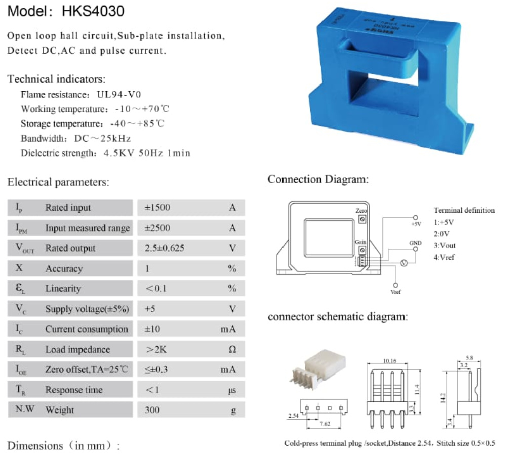
The HKS4030 looks as if it will connect directly to the Arduino analogue input without any other components, but at 600 A rms it is using a little more than half of the Arduino’s input range. That’s not ideal, but not a major problem unless you need to measure below around 10 A, when accuracy will be falling away.
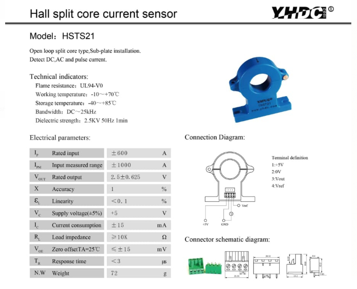
The HSTS21 is rated to 600 A exactly. That (like the HKS4030) is probably a d.c. rating (the clue is the input range is ± 600 A and the output range is ± 2.5 V, and the supply is 5 V, so the output can’t go to 2.5 × √2 V). So it will only measure a sine wave current up to 420 A rms, and if it’s a distorted ‘spiky’ wave shape, a lot less than that.
Not easily and cheaply and off-the-shelf. The problem is isolating the measurement side from the 60 V side, because if you connect the Arduino ground to the negative side of the 60 V and that is not true ground, you can easily get a damaging ‘ground fault’ current.
The best I can suggest is you could put a stand-alone Hall effect i.c. inside a coil carrying a current that is proportional to voltage (i.e. a high resistance coil or include a series dropper resistor), but I’ve never tried it and you would need to experiment to get something that would work, and determine the calibration by measurement.