I have just received my emonPi, and I am trying to set it up with the CT clamps, but I already ran into som questions
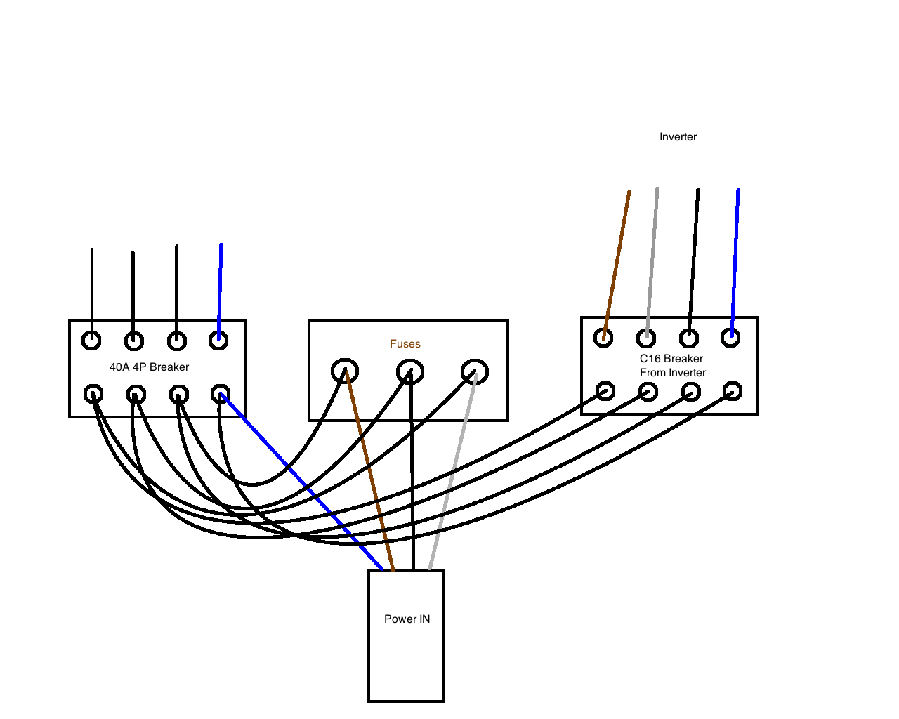
I have created this drawing to make it easier to understand… I’m not an electrician, but I do understand some of it
In the drawing I have just added the main power inputs such as the mains power in, which is three phases.
And the power which comes from my solar inverter, which also seems to have three phases for some reason which I am not aware why… maybe because it is easier to integrate into the mains power in.
My system is able to send power back into the mains if I am in surplus.
My question is about the CT clamps, where do I put them? Right now I have put power1 on the blue (N) cable coming from the mains, and one on the blue (N) cable coming from the solar panels.
My system also has the 9V PSU attached, which I guess it to detect the difference in the sine wave from either the mains or the solar panels?
I have also managed to attach the little pulse eye on my mains meter, whichs pulses 1000 times per kWh.
But at first I would like to measure the correct mains and solar power, so the question is how this is done correctly.
Does the CT clamp measure all three phases when I use the blue (N) cable?
Also is there a way to “verify” this with the pluses from the mains meter?
I forgot to mention, that I have setup my system as a “Type 1” system as per the installation details found on the webpage…
Yet I cannot make sense of the readings, as they do not seem to match what I am seeing on the mains meter (Kamstrup unit), and on my inverter.
The inverter tells me 400W yet the CT clamp reads close to 0 and some time negative readings (I have tried to swap the orientation of the clamp).
Also the readings on the Kampstup mains meter tells me a usage of about 700W, yet the CT clamp tells me only 300W.
I am thinking that using the Neural for the readings may not be the best way in a 3Phase system?
But do I need 6 CT clamps in order to read all 2 x 3Phases? I might be able to add the 3 phases from the solar panels into one CT clamp, but does that work at all? And will it make any differences?
Oh dear. I’m sorry, Heino, but what you have will not work for a 3-phase system. The emonPi was designed only for the UK single phase system.
The problem is, as you suggest, you do need 6 c.t’s, and you need 6 c.t inputs, if you want to measure both the mains power and the power from the solar panels, and you have two on your emonPi. You need 2 x emonTx to do what you want, or you could try an Iotawatt, but I know nothing about that, and it might not be available in the shop when stocks run out. But you can use it to send the readings to your emonPi.
With a 3-phase system, ideally the current in the blue neutral wire is zero! In reality, it is the difference in currents between the three phases. That is why the readings are not sensible.
No, that will be exactly the same as having the c.t. on the neutral cable.
The 9 V a.c adapter is there to give a reference against which the current is measured, so that you can see the direction of power - whether you are using power or selling it back to the electricity company.
The pulse “eye” will record energy that you import, but it will not record the energy that you export (return to the power network).
Hi Robert,
Thank you for the quick reply.
I have been reading about 3P setups, after I wrote my message.
I have actually also bought a emonTX and I have 7 CT clamps in total, so I guess I can get it to work?
I could use the 4 jacks on the emonTx and two on the emonPI ?
I will be kind of a mess, but I think I can manage
I have read that someone has changed their firmware to support 3P, do I also need that, and do I have to do it on both the emonPI and the emonTX?
Or… is it just a matter of adding up the 3 readings from each phase of the mains, and doing the same with the solar inverter inputs?
Only partly.
If you download and install the 3-phase “sketch” (= firmware program) for your emonTx, then that with 3 c.t’s and the a.c adapter will measure power on one 3-phase circuit - either your grid connection or your PV connection.
It will also measure power on one phase (you choose which one) of another circuit provided the voltage is the same - which it will be.
There is no 3-phase sketch for the emonPi (and there cannot be because it has only 2 c.t. inputs). And if you connect the emonPi to 2 phases of a 3-phase supply, then because it has a single-phase sketch inside, the power will be wrong.
There is a way to get current (Strom) but you must change the sketch inside the emonPi, and be sure you do not change it when you automatically update the emonPi!).
If you think you are able to do the necessary changes, I think you should:
Upload the 3-phase sketch to your emonTx, and install inputs 1-3 on your grid connection.
Install c.t.4 on one phase of your PV connection.
Edit the sketch inside the emonPi so that it sends current instead of real power, and upload it. Then, you connect the two c.t’s to the remaining two phases of your PV.
In emonCMS (that is the software inside the emonPi) you will have real power for your Grid connection, and real power for one phase of your PV. You can there multiply the voltage (Spannung) from the emonTx with the current (Strom) from the emonPi to give you apparent power (Scheinleistung) of the 2nd & 3rd phases of the PV.
When finished, you will have true real power imported and exported on your grid connection, and a good estimate of power generated by your PV. From those, you can calculate house use.
I think that is the best you can do with what you have.
It sounds like a solution, but ideally another emonTx would make it a bit easier right?
I have tried to add the CT clamps to the three phases of my PV, and it reads “combined” about 100W shy of what by inverter tells me, but I also haven’t updated the FW to the 3P version yet.
Do I need to add the 9V PSU on the emonTx, the emonPI or both? And does it support 12V? (for some reason I have several 12V PSU’s and no 9V)
Thanks again for the fast support
And, despite my German name I am actually from Denmark, but I understood your German quotes
Either you must get two more 5 V d.c. USB adapters to power your emonTx’s and split the a.c. adapter output so that it feeds both, or you can get a second a.c. adapter. If you will not use the c.t. inputs on your emonPi, then I think a second a.c. adapter. If you will use the c.t inputs on the emonPi, then I recommend 2 x USB 5 V d.c power supplies for the emonTx’s, and split the a.c. adapter 3 ways for the 2 x emonTx and emonPi.
The a.c. adapter can only power one emonTx, but it provide the reference voltage to many - but you must be certain that all 3 connectors are wired the same way.
Your English is much better than my German, but as you wrote that you understood some electricity but you were not an electrician, I thought the German might help.
If you are getting more emonTx’s you are better off using each one as a single phase monitor than using them each as 3phase monitors at different points. So you shouldn’t need to change the FW.
If you are running emontx’s in close proximity to a emonpi you may want to consider connecting them by USB-serial adapters rather than by RF, the results will be better and the 5v power will be provided via the emonPi rather thane the AC:AC adapters.
Yes, what Paul says is correct - but I did not know you might have 3! You might want to buy a programmer, which will allow you to edit and load the firmware in the emonTx, which I think you might need to do. Also, when you order your emonTx’s, ask for one to be programmed with a different Node ID. There is a switch to select either Node 8 or Node 7, but the third will need to be Node 9. But to make one Node 9, you need a programmer to do it yourself, or the shop will do that for you.
If you have one emonTx per phase, you must also have 3 x a.c adapters - one for each phase.
Thanks for the input Paul. I need the third emonTX in another part of my house to measure the power used for a IT Rack I have… it’s just one phase, and I guess I can do this without the AC PSU.
I have already programmed the 3P firmware to my emonTX, and it seems to work, yet now it has gone dark and I have no power on my PV… (is shows negative values from 0 to -10).
I will have to wait for daylight to continue this project
Thanks again, and I will keep you updated of my progress.
I would still consider using the emonPi and 2 emonTx’s for your 3 phases then. The 3phase emontx solution is only really for when you have no choice. it’s a good tool to back good of a bad position. It is no where near as good as a “per phase” install and you have enough devices to do a proper “per phase” install.
I expect that the IT equipment will boast some of the poorest power factors in the house, so if there is anywhere you need an AC adapter it’s there. You need to power the emonTx somehow so it would be daft not to use a 9vac rather than a 5vdc adapter.
Normally most poor PF loads are quite small and the inaccuracy gets lost in the much bigger high PF loads and don’t effect the overall accuracy. If you are measuring just low PF stuff alone, there is no where for the inaccuracy to hide and you just get inaccurate results.
That is normal, it’s the inverter drawing a little power of the grid to stay awake etc, if your inverter has a sleep function that might disappear after an hour of low/no production, otherwise you will have to remove it in emoncms if you don’t want to see that, many users do.
I will use two of the emonTx’s for the 2 x 3 phases, one for the mains, and one for the PVs.
The reason why I swapped the FW to the 3Phase one, was that the measurements of the 3 phases combined were out about 100W compared to my inverter. I will see tomorrow if it has fixed anything. I might also try to fit the CTs on the mains, so I can do some testing there as well.
I agree with the AC adapter, and I have ordered them with the new emonTx’s.
But you are telling me that I should rather stay on the initial FW rather than the 3Phase version?
I know you have one emonPi and 2 emonTx’s at the dist board but for the sake of simplicity here imagine you have 3 emonTx’s.
With 3 emonTx’s each on a different phase with an AC input, all CT inputs (3x4=12) are accurate because they have a factual AC waveform to reference and determine real power.
With 3 emonTx’s each running a 3ph sketch and only one ac adapter, at very best you have 2 CT’s per device that have access to an actual waveform to use and the other 2 CT’s are best guestimates, so only 50% (max) of your CT’s are accurate. if you are unlucky with positioning of mains sockets etc it could be as low as 25% of CTs accurate and 75% guesstimated.
[edit - (for example) Your solar inverter should ideally be monitored by a CT from each device, each device will be able to give an accurate value for that phase at the inverter, summing those 3 inputs in emoncms will give the greatest accuracy. Don’t get me wrong many users do it the way you are proposing (many because they have no choice) and they get good results, but that is often partially down to luck and the law of averages, since a 3ph sketch and a single AC adapter cannot be guaranteed to be accurate over all 3 phases. So don’t be put off if your minds made up, but you should be aware of what you’re getting and that you do have the equipment for a better result]
So you are telling me that the most accurate way would be with 3 emonTx’s each with two CT’s connected, one to the mains L1, and one to the PV’s L1, and you want me to put the AC adapter of each on the same phase as well? I can see that it makes it the most accurate, but I also have to have an electrician to make me some outputs for the other phases for the AC adapters. Currently I one have one phase where the emonTx’s are installed. But if that’s what it takes, I guess I might consider it, as I have other small project for the electrician anyway, such as to make space for the CT’s to mount better
Another quick question… I have put one of my CT’s the wrong way up, so that it reads a negative value now, is it possible to fix that in the feeds? like multiply with -1 ?
I tried it, but it looks like it doesn’t work, or maybe I’m doing something wrong
That unfortunately is often the case, but since you’re at the dist box it is often quite a simple job (for an electrician). Since the ring mains are usually well “ring” they can often take a tail out of the circuit breaker re-route it to a socket mounted next to the dist board and just add a short bit of cable from the socket to the breaker to complete the ring again and that’s it without having a new breaker fitted.
Yes you can do exactly that, either in emonhub in the scales settings or in emonmcs, the former will correct the data before distributing it, the latter will only fix it in that location, so if you have 2 emoncms, you will need to do both or once in emonhub.
@pb66 I doubt that Heino has a “ring main”, as he is in Denmark. He will almost certainly have radial final sub-circuits.
Let us go back to why the 3-phase sketch is not the best. It is simply because there is only one actual measurement of voltage, the voltage for the other two phases is derived from the voltage of the first phase. If all three voltages are identical in amplitude, that is not a problem, but in practice, they will not be. So although the current is measured accurately, the power may be wrong because we can only hope that the voltage will be the same across all three phases.
If you use one emonTx on one phase only (with the standard single-phase sketch), it knows the voltage of that phase, so it can calculate all four powers accurately.
And just to clarify, if you use the wrong sketch on the wrong system, the voltage and current can be around 120° apart and then you’ll get totally wrong powers, you’ll read about half the correct value when the voltage and current are on different phases.
My 3-phase “Mk2” PCB will allow real power to be properly measured in a three phase environment. It monitors the three separate voltage sources and uses three CTs, one per phase. The resulting data can be transmitted by RF just as for the emonTx. http://mk2pvrouter.co.uk/61101.html
Hi Robin,
Sadly I have already ordered some more emonTX modules, and I am eagerly awaiting them
But your PCB also looks nice. I guess I will not need the three AC/AC PSU’s as with the emonTX setup?
I would still need two PCB’s, right? One for my 3 phase mains, and one for the 3 phase PV ?
Right now I have the CT clamps on the 3 phase mains, and I am able to see when the power is exported (on a sunny day), as it shows me a negative current, so I have enjoyed that the last few days.
I guess the pulse counter isn’t much good at I have noticed that my meter (Kamstrup) also blinks as I export power…

