Using an SCT-013 to calculate "low overhead" instantaneous power monitoring, is this method missing something?

Hi, first time poster. I’m working on a pool controller project, based on a particle.io photon (Arduino-like). I am currently adding “power monitoring” for my pool filter pump and Stenner pumps, which are pumps that add acid and chlorine to the pool. All I really need is the wattage being consumed at any given time by those devices. I am a retired electrical engineer with chip design background so AC fundamentals are definitely NOT a forte. I think I have a solution that works, but I am unclear if I am missing something obvious.

I am using a couple SCT-013’s to accomplish the hardware portion of the project…setup exactly as described in this tutorial.

https://learn.openenergymonitor.org/electricity-monitoring/ct-sensors/interface-with-arduino

I started looking at the openenergymonitor library which has been ported to the particle.io Photon, but there seems to be a lot more there than I need (??)…I am also concerned about the “blocking nature” of the code (large number of consecutive A/D samples required), as all my other code is written in a non-blocking manner.

So I wrote some code which seems to do the job, but I really don’t understand all the intricacies of realPower vs apparentPower and powerFactor. So I might be missing something or possibly run into a problem when I use this code/hardware for my 220v pool filter pump (Stenner pumps are 120v).

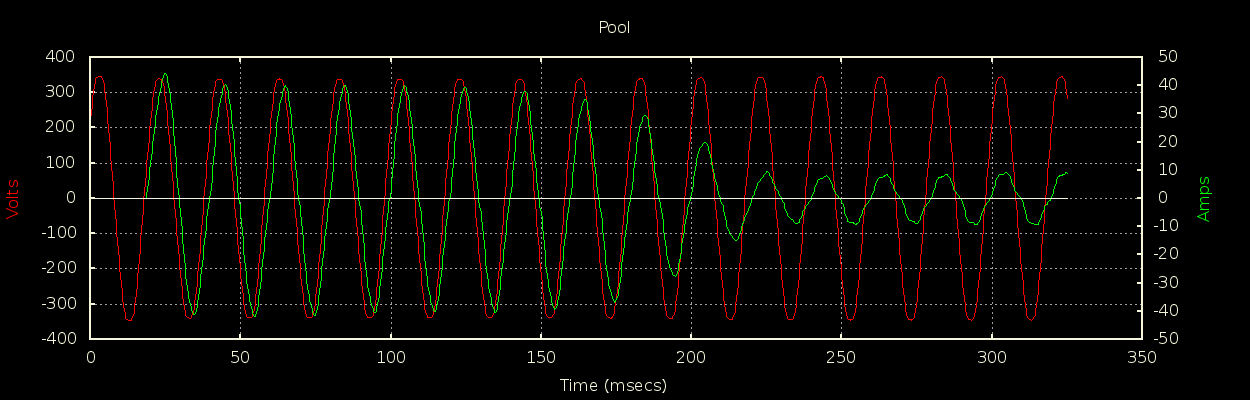
The code does ~20 strategically timed samples of the SCT-013 60Hz output over a period of one second. These 20 samples contain 16 equally spaced points of the 16.7ms period of the 60Hz signal. The peak-to-peak values (high and low) are extracted from the code and a constant multiplier converts it to a current (amps) value. Then it is multiplied by the voltage (120v) to get watts.

I have only tested this on combinations of 120v “appliances” but it seems to be accurate (matches my Kill-A-Watts meter well within one percent) for all my test cases (0-600 watts). It does mismatch at the very low end (<20 watts).

Am I missing anything with this simplified approach? I am enclosing the code below…I am not very familiar with the Arduino so there might be some things in there that don’t translate directly (the A/D read on analog pin A0 in particular).

Attaching an .ino file.

SAMPLE OUTPUT

Serial connection closed. Attempting to reconnect…
Serial monitor opened successfully:
Reading Min: 0, Reading Max : 0, Reading Diff : 0, Current (amps) : 0.000000, Watts: 0
Reading Min: 1915, Reading Max : 2146, Reading Diff : 231, Current (amps) : 0.370172, Watts: 44
Reading Min: 1911, Reading Max : 2145, Reading Diff : 234, Current (amps) : 0.374979, Watts: 44
Reading Min: 1913, Reading Max : 2145, Reading Diff : 232, Current (amps) : 0.371774, Watts: 44
Reading Min: 1915, Reading Max : 2142, Reading Diff : 227, Current (amps) : 0.363762, Watts: 43
Reading Min: 1917, Reading Max : 2146, Reading Diff : 229, Current (amps) : 0.366967, Watts: 44
Reading Min: 1913, Reading Max : 2144, Reading Diff : 231, Current (amps) : 0.370172, Watts: 44
Reading Min: 1915, Reading Max : 2141, Reading Diff : 226, Current (amps) : 0.362160, Watts: 43

/* This sketch demonstrates a method to dynamically calculate current and 
 * power (60Hz) using a current transformer, such as a SCT-013, with low 
 * code and execution time overhead.  It is non-blocking such that photon/arduino 
 * processing/adc-conversions are spread over a period of time.
 *
 * @60Hz, three cycles take 50ms, we will sample the SCT-013 at a frequency of 49ms 
 * (about every third cycle) in order to slightly change the sampled position on 
 * subsequent cycles (by 1ms each time).  This means we would need 16-17 samples to
 * characterize "one complete" cycle (which takes 16.67 ms). 17 samples @49ms is 843ms 
 * which means we can sample/calculate a new current/power about every second with
 * low overhead.  
 * 
 * The code "main accomplishment" is to simply find the peaks (high and low values of the 
 * sine wave) for the amperage signal coming from the SCT-013. These are then used to 
 * calculate instantaneous current and power. 
 * 
 */

#define SCT013_SAMPLE_TIME 49  // 49ms
#define PUBLISH_TIME 1000      // 1000ms = every second
/* The following constant is experimentally determined using an ammeter: 
 *     = (Reading on amp meter) / differential
 * "differential" is the variable printed out below
 */
#define CALIBRATION_CONSTANT  0.0016024759284732F  


// for now...they are all global
unsigned long currentMillis, prior_sample_time, prior_publish_time;
float amps;  // amp reading
uint16_t differential, wattage, recent_sample, prior_sample, current_min, current_max;
bool isFalling;
uint8_t sample_count;


void setup() {

}


void loop() {

  currentMillis = millis();

// Take & compare a current (amperage) sample every SCT013_SAMPLE_TIME (49ms).
  if ((currentMillis - prior_sample_time) >= SCT013_SAMPLE_TIME) {

    recent_sample = analogRead(A0);

    if (isFalling) {   // consecutive amp samples are "heading down towards" a sine-wave minimum
      if (recent_sample >= prior_sample) {  
        isFalling = false;      // amps sine-wave minimum was reached on prior_sample, now heading back towards a maximum
        current_min = prior_sample;
      }
    }
    else {            // consecutive amp samples are "heading up towards" a sine-wave maximum
      if (recent_sample <= prior_sample) {    
        isFalling = true;       // amps sine-wave maximum was reached on prior_sample, now heading back towards a minimum
        current_max = prior_sample;
      }
    }
    
    prior_sample = recent_sample;
    prior_sample_time = currentMillis;     // Next Sample Time Setup...use currentMillis rather than millis() to insure proper spacing

    differential = current_max - current_min;  // peak to peak value, raw and uncalibrated
    amps = differential * CALIBRATION_CONSTANT;  // forget about the .707 multiplier RMS stuff...just incorporate it into the constant
    wattage = 120 * amps;
  }


// Print the latest available amperage/power values every PUBLISH_TIME (1 second)
  if ((currentMillis - prior_publish_time) >= PUBLISH_TIME) {
    Serial.printlnf("Reading Min: %d, Reading Max : %d, Reading Diff : %d, Current (amps) : %f, Watts: %d", current_min, current_max, differential, amps, wattage);
    prior_publish_time = currentMillis;
  }

}

Hi John, and welcome aboard!

Your user account has been bumped up a notch, so you should be able to upload your sketch now.

When you upload a code snippet, wrap it in three backticks like so:

```
code
```

It’ll look like this:

code

which makes it easier to read

Thanks!

Thanks Bill! I updated the original post.

YW,S! thumbsup

I recently posted a quick explanation here: Understanding units - #2 by Robert.Wall

What we do in emonLib is sample the whole waveform - for me in the UK, there’s about 55 sample pairs (voltage & current) per cycle, but rather fewer for your 60 Hz mains. We can then accurately calculate the average power (if you also supply the voltage waveform) or the true rms average current.
What you’re doing, when you just pick off the peak value, is you are relying on the shape of your current wave staying the same, and knowing the shape of the current wave so that you can calculate (or fix by trial and error) the rms value knowing the ratio of that to the peak value.
There are two further sources of error: your voltage won’t always stay at exactly 120 V, and the power factor of your pumps will be significantly less than unity, which means that the “power” - actually apparent power - you calculate will be greater than the real power you pay for.
Provided that all these things remain constant, and they are likely to remain reasonably so in your particular circumstances, then you should be able to adjust the calibration to correct your readings. And it would appear that you have succeeded in doing that:

But in general, the power factor of the load - say your whole house - will change according to the types of appliances you have operational at any time, and the voltage won’t remain at 120 V exactly.

That is most likely due to the c.t. you’re using - its accuracy is only specified down to 10 A - and you’re probably also adding some electrical noise picked up and measured along with the current you’re trying to measure.

So the answer to that is - generality. If you change the pump motor for a different size or make, or use your monitor on something other than that particular pump motor, you will need to re-calibrate it because the assumptions inside CALIBRATION_CONSTANT will be wrong.

Robert, thanks for the detailed reply and for the pointer to your explanation about Real Power / Apparent Power. It makes sense at a high level but…my eyes still glaze over, haha.

In any case, my desire for power monitoring on this pool project is not for “billing/charging”, it is for comparison purposes to known good values and will generate alerts if the system is operating differently than expected. It will also be used for efficiency comparisons of gpm (pumped volume of water) vs power required…Energy Factor in pool pump terms. So maybe it will be OK for my usage model, even with expected variations in voltage and equipment changes.

However, I AM worried about one aspect of my solution that I thought about after posting. Whereas emonLib takes 110 samples over one cycle, my code takes only 20 samples over 60 cycles. In this small sketch, it is easy for those samples to be taken as expected, spaced out exactly where they are intended which allows me to easily capture those peak-to-peak swings.

But in my final solution where this"sketch" is incorporated into the much larger pool controller firmware, I am not yet sure that those “spaced samples” will occur as expected which could definitely cause inaccurate captures of those min/max values. If I have a problem, I guess I could consider using interrupts to ensure samples are taken closer to those “spaced slots”.

Finally, the SCT-013 I am currently using is a -020 (20 amp max) . It limits me to a 1 volt range for the readings. I have ordered the -000 version so that I can more suitably expand the range of the readings for higher resolution. In my current test setup, I have run four loops of the measured wire through the SCT-013-020 and that may explain why I am getting pretty decent results near the low end, but not under 20watts.

Thanks again for your help.

If you’re worried about timing with your larger controller firmware, a simple solution is to off-board it :slight_smile:
Get an Arduino pro mini or the like (basically the same chip as in the EmonTx) and connect it up to your particle (use I2C, SPI or straight TTL serial, depending on what you have spare in the particle). You can leave the pro mini just running continuous samples and query it every now and then for an updated power/current reading.

As an aside, how are you measuring pumped water volume?

Greebo…I originally started my pool controller project with the goal of having just one chip (only the particle.io Photon). Well, this project has become an enjoyable hobby and it has since expanded a bit, so I am definitely open to your solution (adding another controller) if/when I hit a roadblock.

Here is a link to my project progress updates if you are interested:

About the gpm measurement…I currently have a FlowVis in my system which I believe is very accurate, but can only be manually observed…so it doesn’t help directly…

…but there is a way to estimate gpm using using psi gauges, head calculations, and charts. I have some really nice PSI gauges in a few places for my pool controller system including at the pump suction/return…so I could do that…

http://www.inyopools.com/HowToPage/how_to_measure_total_dynamic_head_with_gauges.aspx

But I am not really happy with those estimates so…my plan is to completely characterize the “head“ in MY system (for all desired rpms/configurations) and chart my system’s actual gpm (via FlowVis) for all points. Once I have this data, I will curve fit equations to the measured GPM so that I can dynamically (and I believe accurately) calculate the GPM using the PSI readings obtained from my pool pump suction/return. I expect to end up with about 6-10 equations (differences in RPMs & configurations), of which only one would apply at any given time.

As you can see, this “hobby” has become a bit obsessive, haha.

Alternatively…one could wait for this (a product announced, but not seemingly available)…apparently it has a port that can be read to get the GPM data directly…but it would ruin some of the fun…haha.

1 Like

You might want to look at MartinR’s energy diverter. Learn→PV Diversion→PLL Diverter
Not of course as an energy diverter, but the measurement is phase locked to the a.c. waveform. You need a voltage input for it to work. The principle is a sample close to the zero crossing is measured, and the amount it is away from zero adjusts the timing of the loop, so that you get an exact number of samples at exactly the same point on the waveform each time. You could have four samples per cycle (that’s the simplest concept), one would be at the positive-going crossing, the next at the positive peak, then the 3rd sample at the negative-going crossing and the final sample of the cycle at the negative peak. There’s a big snag here: remember, the peak current won’t be exactly ¼ cycle after the zero crossing of the voltage due to current lagging the voltage, and that’s because your pump will be inductive; and you can’t lock to the current because it goes away when the pump is switched off, and it takes the loop a second or two to lock when it starts up.

You need not measure every cycle. Depending on how stable everything is, you could lock to the zero crossing every 5th cycle say, then time the two peak-reading samples of current at an adjustable time later - the first nominally 4166 µs after the crossing but adjustable to find the peak, and the second exactly 8333 µs after that.

Despite you thinking emonLib blocks, in normal use it actually samples for only 200 ms every 10 s, so in fact the processor is largely free for 98% of the time.

Robert, thanks for the suggestion about looking at that PLL solution. I was a digital logic EE, so much of this stuff is a stretch for me…as is programming. That solution seems like it would work very well for me, but I am going to try and avoid adding more hardware at this point, at least until I hit a roadblock with this current direction.

Those numbers are actually much better than I expected based on my glance of the emonLib. But seeing those numbers triggered a perusal of my own firmware. I realize that I will definitely NOT be able to sample reliably like my sketch because my loop() sometimes takes 10’s of ms (30-50) to execute on some occasions which would mean I would miss the sampling windows.

A particular culprit for me is the OneWire bus protocol (used for DS18B20 temp devices) which is implemented in software and requires 10ms+ for some transfers, more when multiple transfers are required. It is not read often, but would definitely cause problems for my sketch.

In any case, some of the investigations I plan involve my pool’s In-Floor-Cleaning-System and the impact it has on Energy Factor/efficiency of pool operation during the time it is running. The pool pump runs at a constant RPM but the flow (gpm) and pump PSI change dynamically and dramatically as popups on the pool bottom rise and fall. Pump wattage is also obviously changing dramatically.

My plan is to eventually characterize what is happening to the power and gpm in those roughly “10 second” transition zones between plateaus. I don’t know yet if new power readings every second will get me close, but I want to give it a shot.

So, since I have realized my sketch will not work as written once integrated, I am going to move to using interrupts to take analog samples at particular times…but still with a similar methodolgy. I’ll report back whether it works or not. The term on the Photon is “Interval Timers”, I think the Arduino has the same concept. All of this is new to me, but I am having a blast.

Thanks again for the input!

Just a heads up that the power factor of my Onga pool pump varies significantly with load, so any short cuts you take in measuring power will likely come back to bite when as you say…

It’s not just Real power that changes dramatically, but also power factor. In other words, the Real / Apparent ratio you’ve baked into your calibration will be changing from under you as the load on the pump changes.

[EDIT} - to put some numbers on that so you can decide whether it’s significant enough to disturb your plans, I’ve got two common valve settings on the pump input and output; the back-pressure on the pump output is quite different between the two settings. On one setting the pump uses 994W while drawing 4.270A, on the other setting it uses 1195.7W while drawing 4.963A so a 20% increase in power but only a 16% increase in current.

Also keep an eye out for much higher currents during the pump start up stage, so if you zoom in too much you might get some pretty high voltages for several cycles. Here’s the current draw for my pool pump starting up:

you could always try analog temperature sensor (ntc 10k) and analog multiplexer or analog chip and build a simple temperature board and you would not have to worry about changing rom ids of DS18B20

not sure how fast you want to loop. but you could build RRD array and say based on 5 loops and then average the temp over that time frame for a rolling average or block count for fixed average

We’ve pointed out the pitfalls associated with John’s proposed “low overhead” approach - there’s little more that we can do. I think whether it works or not depends on the definition of “works” and the expectation - or maybe the acceptability - of the accuracy of the method that’s finally chosen.

dbc…thanks for the additional information! I don’t know yet if those kinds of discrepancies would “kill” my effort to try and characterize my In-Floor-Cleaning-System or not. I am still trying to digest all this information with very little previous data/experiences. Do you have a single speed pump on your pool? Those numbers seem to indicate just changing the valves for a different flow path using the same RPM setting on your pump. I actually have a VSP pump, don’t know if that makes the considerations better or worse?

Good point…I quickly hit my current limit (on my 4-loop 20amp SCT-013 test circuit) when I tried out a hair dryer today. I made it a 3-loop but it still doesn’t handle the high settings. Your scope of the pool pump current at startup is an eye-opener. Do I have to be concerned about the negative voltages (and I suppose also the high voltages) ruining the analog input to a chip if the currents through the burden resistor are much higher than expected?

Both you and Robert mentioned this and I really didn’t understand the references until I did a bit more reading and experimenting. In Robert’s case he indicated that my calibration might work for the calibrated pump but probably not work for another.

I don’t think my calibration constant is what you two are thinking…it is more in tune with your calibration procedure for the emonLIB calibration:

emon1.current(1, 111.1); // Current: input pin, calibration.

…or the procedure described here

https://learn.openenergymonitor.org/electricity-monitoring/ctac/calibration

I say that because the only thing I had tested up to today has been resistive loads (crock pots, lights). I didn’t understand the need to compensate for Real vs Apparent Power, so my correction factor doesn’t do anything to try and get more accurate readings for an inductive load. I just needed my current readings to match the ammeter for the resistive-type loads I was measuring.

stephen, thanks for the suggestion. I have found, though, that my previous approach of trying to “time” samples will NOT be possible even without that DS18B20 “culprit” haha. My pool controller firwmware’s main loop() contains so many possible branches that are conditional, it would be impossible for me to rely on any sort of timing within it.

AND, I also love those DS18B20 devices!!! Five for $17 (with probe/cord) and the they all work great!!! I am just amazed that someone thought up, and then actually marketed, a one wire bus (actually two with ground, or an optional third with a power source) interface. I have been out of the industry for about 20 years but I couldn’t believe it when I “discovered it” a couple years ago. So NOPE, I wanna keep those, sorry :smiley:

Hey Robert, don’t give up on my yet :wink: I am coming up to speed, slowly…I still have lots of issues and probably lots of questions. But you are right, it will come down to acceptability for what I think I need or possibly, can get by with.

I did get a hair dryer out today and measure the wattage of that with my setup. And, lo and behold, the numbers did not match like all the resistive loads that I had measured, as both you and dBC indicated. I used a Kill-O-Watt type device (actually a Kuman) to compare my “watts values” to but am unclear whether or not they are designed to somewhat adjust for the Real Power. Based on the mismatches, it seems there is at least an attempt to do so.

Anyway a few results:

watts-meter mine
160 170 low speed
296 308 high speed
500 537 low speed with heat
high speed with heat maxed out, i previously put the wrong values in there, reversed.

I imagine I will see higher differences and variations with the pool pump.

Mine is just single speed. I haven’t fully characterised it but it seems the more water it’s moving, the more power it consumes and the closer it gets to unity power factor. Partially obstructing its output makes the pressure at the output go up, the volume of water moved go down, the power consumption go down and the power factor go down. For an extreme demo, if you run it dry on the bench with no plumbing attached (not recommended for long as it will burn out the pump mechanism) it becomes extremely reactive… I think I’ve seen about 550 VAR in that scenario… so lots of amps, but not that much real power being used.

It may well help. If they’ve implemented that with an inverter it may even have some power factor correction built in. You might be able to use your Kill-a-Watt to characterise it further. Mine is a very simple synchronous AC motor.

Yes definitely. Some external protection by way of a small series R and some protection diodes to GND and Vcc should take care of it. If you ever get a locked-rotor fault on your pump (may not be possible with your variable speed smarts) it can sit there drawing heavy currents for an extended period… about 40A from memory on mine.

That all sounds pretty much as I’d expect from an induction motor, even though I’m not an electrical machines expert.

@jonpcar [quote=“jonpcar, post:16, topic:14732”]
I used a Kill-O-Watt type device (actually a Kuman)
[/quote]
If it’s a KW47, from the website:
"Various Parameters: Power(W), Energy (kWh), Voltage, Amps, Power Factor, … "

Not “adjust”, I would expect it to measure voltage & current samples in very much the same way that emonLib does, and from each of those pairs of samples it will calculate the instantaneous real power, and over some time period (one cycle of mains at least) it will average voltage and current to get the rms values, average the powers, then calculate power factor from those.
It says it displays (real) Power, Voltage, Current & Power factor - but over 3 display modes

Look at Power Factor - that’s the ratio (real power) ÷ (apparent power), and apparent power = voltage × current.

If you use it on a resistive load, it should read p.f. = 1.0, and if you look at voltage, current and power, they should work out as power = voltage × current.
Now try it on your hair dryer. The presence of the motor will spoil that and power ≠ voltage × current, but you’ll find power = voltage × current × power factor. (All to within the unit’s accuracy limits, of course.)

Robert, on the box it has a very small KW48, but it does have all the features you found and I tried them out. Seems to work and the pf does show about 0.9 for the hairdryer. The resistive loads are 1 (or very close) as you expected…so it seems to work.

I will be able to use this on my Stenner pumps (120v) but not on my pump (220v)…unless there is an acceptable way to hook it up to one leg and the neutral…is there such a way? Maybe that requires an adjustment to its calculation?

In any case, I do have a watts reading on my pump which I will use to compare my “relatively static” watts cases to: such as skimming but NOT when running my IFCS (In-Floor-Cleaning-System).

dBC, this is probably more than you want to know, but here is a graph of my IFCS PSI gauge during the time where my cleaning system is running. The filter and pump PSI gauges are similar, but at slightly higher levels.

The plateaus represent the time when one of my IFCS zone’s popups is “blasting out water” to stir up the bottom/walls of the pool so that dirt can be suspended/filtered. The valleys are where it is switching to the next zone and therefore two zones are “on” simultaneously for a short time

When two sets of popups are ON, the pressure is less, the GPM is higher, and the power is of course higher. Popups have 12 positions (30 degrees each), and each time they pop up, they rotate to the next position. From the graph you can see that for one cycle through my 5 zones, it takes about 5 minutes…x12, it takes about an hour to “sweep” the entire pool once. That’s as fast as it can go, the switching is controlled through a water-wheel and some gears…but in reality, it is still too slow. The “blasting out water” from one set of popups doesn’t need 30 seconds (plateau) to accomplish its task.

So, I am planning to double the speed of my sweeping through a trick, using an automated valve, I will be creating a valley in between each of those existing valleys. That will force an additional rotation of the popups and allow the pool to be swept in half the time. So you can see that the gpms/power/pressures are all going to be very dynamic during this operation. Do I really need to characterize it? Probably not, but I am interested in doing it.

Probably not. You need to know which leg (line or neutral) the current measurement is in, and then arrange for the other one to connect to neutral, then double the voltage and power values, but not of course the current and power factor. That’s going to be risky at the best of times, I’d be VERY careful trying something like that, and I’m used to working on live equipment. If you’re really interested, I suggest you buy another European version that’s good to 240 V.

1 Like