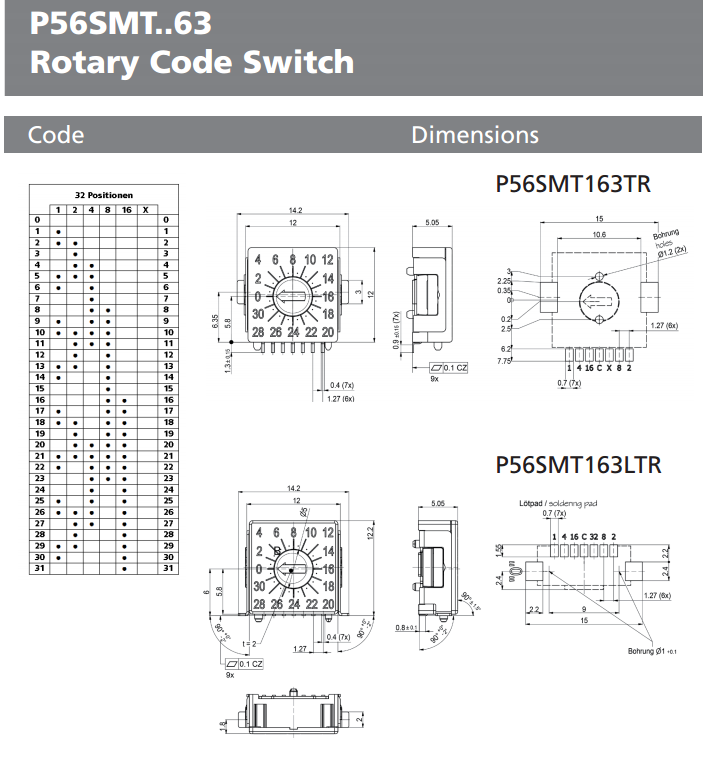
A bit pricey for my needs but this 32 position (5 pole) rotary dip switch, setting a node id couldn’t really be made any simpler…
It’s an encoded switch. Would that be an issue?
I’m thinking something along the lines of BCD, since 2^5=32.
I understood that to be it’s strength. utilizing only 5 contacts to produce the 32 options/nodeids. rather than 5 spst dip switches and the user needing to set the nodeid in binary, with the 32position switch the user just “sets the nodeid” ie 0 - 31.
Looking at the contact arrangement (despite the pins being labelled 1,2,4,8,16 & Com) the output doesn’t appear to be binary and would require the sketch to lookup the nodeid from an array (using the switch position as an index) AFAICT still do’able and very user friendly, just a bit cost prohibitive IMO.
The same for the CT scaling, a rotary 4 position switch is labelled 0-3, and sparkies tend to think in terms of “loops” rather than passes of the CT (this can be an issue depending on the position of the CT 2x loops can be either 2 or 3 passes) but dialing in the number of “loops” maybe the way to go, it maybe easier to ensure they always put the ct at the “root of the loop” and take the use of binary switches out of the equation, just “set the number of loops” 0-3.
Ideally I would like 0-4 loops for ranges 0 to 100,50,33,25,20, but that requires an additional pin per ct (not very efficient use of binary, 3 pins gives 8 options of which I would only use 5) and 3 pins x 5CT’s =15pins, that’s almost a whole 16bit device of it’s own without a node id, so even more cost.
For now I will just go for 2 x 8way dip switches for some evaluation tests.
I don’t see any obvious issues there. When the ESP is flashing the AVR the AVR won’t be running any code, and all the SPI /CS signals should be pulled high by external pull-ups, so they won’t be listening or interfering. Once the ESP has finished flashing it will need to do the equivalent of unplugging itself from the ICSP header, presumably by gently pulling high all the signals running over to the AVR. So you don’t really have two SPI masters, you really only have one (the AVR), and you also have an ISP programmer, which could be an AVR-ISPII or it could be an ESP running some software.
I’ve got 8 devices on the SPI bus in that energy monitor pictured above, and I don’t have any problem programming it with the AVR-ISPII via the ICSP header. The AVR half of your design shouldn’t really know or care what you’re “attaching” to the ICSP header. An AVR-ISPII or a hardwired ESP should look identical (provided it disappears once flashed).
You’ll need to take a bit of care with the /CSs if you plan having more than one device on the SPI bus. Do you intend using the RF module as well as the input mux? You’ll probably find that both the RF library and the MCP23S17 library assume exclusive use of D10 (on an Uno) for the /CS controlling their device.
That’s good to hear about the SPI(s).
I hadn’t thought about the potential clash of Libs for the clock, it was obvious I would need a separate SS (and had opted for picking up the D20 from the back of the unused RJ45p8 because everything else is taken).
I don’t really use RF at the moment, I did do one not so long back and I pinched the rfm.ino @Robert.Wall put together for the 3phase sketch as I needed something lightweight as i am using a sketch based on MartinR’s PLL code, so it may not be quite as big an issue as there is no JeeLib to deal with, even when I do use RF.
So it looks like the “MCP23S17 Class for Arduino” is intended to run at 8MHz and the rfm.ino at 2MHz?, the datasheet for the MCP23S17 table 2-2 states a MAX Clock Frequency of 10MHz. Would it be a simple case of slowing the “MCP23S17 Class for Arduino” down to 2MHz? or is thar just wishful thinking?
For the moment the “MCP23S17 Class for Arduino” would get priority as I rarely use rf, but, The settings will only be read at the top of setup(), so the “MCP23S17 Class for Arduino” would be done’n’dusted and the SPI could be closed before the rfm opens it again at the lower speed.
No, it’s Gray Code - designed so that only one bit changes as you move between adjacent switch positions.
D’oh! I forgot about Gray code.
For some silly reason, and I knew it wasn’t EBCDIC, the only other code I could think of was EBCDIC.
You should be able to just run all devices at the slower clock speed if SPI performance isn’t an issue for you. Actually, that rfm.ino reference does a DIV8 at init time, but then overrides that with a DIV4 each time it selects the RF module (see line 140), and the comment down there suggests it used to use DIV2. I’ve no idea what they mean by a SPI stall, there is no handshake so a SPI cycle always completes with or without the slave. It’s probably a reference to some higher-level stall, like a DONE bit in some RF module register not getting set or something. Reading between the lines, it seems nobody is quite sure what speed you can run the RF module at.
But that select() routine demonstrates you can program clock speed and data mode up on the fly, so if you want to run each SPI device at it’s maximum permissible speed you easily can. That’s the approach I take with 8 devices on the bus. I follow some simple rules:
. never do SPI transactions at ISR level
. let each f/w subsystem configure the SPI parameters just before it transacts
Another curiosity in that RF code is that it disables interrupts from the select() right through to the unselect(). I’m not sure I could tolerate that level of latency. Well behaved SPI slaves put no maximum timing requirements on the transactions and are driven solely by what SCLK does. It’s not clear whether that long disabling of interrupts is because the RF module is not so well behaved or they’re worried that some other subsystem might try to do SPI transactions inside an ISR.
On the upside, both of your SPI subsystems look like they’re well set up to allow you to choose which /CS pin they use. It looks like you can just redefine RFMSELPIN for the RF module, and specify the pin in the second parameter to the MCP constructor in the MCP code, so I take back what I said earlier about them assuming D10.
[EDIT] Oh, and I just noticed that changing that clock_divider (2) define you referenced in the MCP code won’t make any difference. They helpfully define it at the top of the file to make you think that’s where you can change it, but then don’t use it! (The code that did is commented away).
For info, the RFM69 code in the 3-phase sketch was lifted straight out of JeeLib, all I did was strip out all the subroutines and make it essentially all in-line, as we only required the transmit function with very limited set of options and capability, and most features of the library were unnecessary for us.
I didn’t go very far in analysing all the details, for the very good reason that it works and maintains a clear link with JeeLib for (hopefully) assured compatibility with the library at the receive end.
Quick update!
I now have a MCP23S17 and a couple of 8way dip switches sat on my desk, when I get the opportunity I will have a play and see what happens.
Paul,
I’m a bit late to this discussion, and it looks like you may already have a workable solution.
But looking at your original sketch, I think it should be possible with one or more octal 3-state line driver IC’s (74HC240, 241 or 244 maybe).
Instead of switching at the MCU pins, buffer the DIP switch outputs and GPIO “main” function pins at the IO connector (depending on each pin’s direction and tolerance to spurious stimuli).
These IC’s are pennies each, so it might be a cost-effective solution.
Thanks for the suggestion, I will bear it in mind. But for now, I think I’m sold on these SPI IO expanders. And as for the cost, the 2x basic 8way DIP switches cost more than a single IO expander chip.
Just discovered that it seems these IO expanders can share the same SS/CS and are then addressed directly using the device ids set (0-7). So I can actually have up to 8 of these, which is up to 128 switches at a cost of one single DIO pin on the AVR.
What I would now like to give some consideration is how to combine the use of say, 2 burden resistors and 2 higher grade DIP switch contacts per CT channel, to give me 4 different CT ranges AND automatically alter the calibration const based on the switches.
I suspect it would have been pretty easy if burdens were connected to gnd rather than a midrail as I’m guessing the weak pullup of the IO expander input wouldn’t effect the burden’s operation.
Any good idea’s welcome on how to pull something like that off?
EDIT - Time to change the thread title I think!