I am looking at reading higher current reading with a PZEM-004T energy sensor but I am not able to find any specks on the sensor that Indicated what the Maximum current is that the sensor can handle from the ct. I am looking to get a 500A - 1A ct clamp. Wil I be able to or will I blow the sensor?
I think it is highly likely that the 1 A secondary current (at the rated primary current) will be far too great for the device. Can you measure the secondary current of the supplied c.t?
If you know that, and the burden that the PZEM-004T presents to the c.t, you could use a second burden to divert the major part of the current away from the PZEM. But if you get it wrong, you’ll blow it up just the same.
[Edit]
What I’d do is measure the input current: feed a low measured current into the PZEM and see what it reads - starting very low - say 10 mA and gradually increase the current until it reads about half-scale. Then you can infer the full-scale input current and the calibration.
If you check the voltage across the PZEM at the same time, you know its resistance, and you can calculate the shunt resistance needed to divert the rest of the 1 A away from the PZEM.
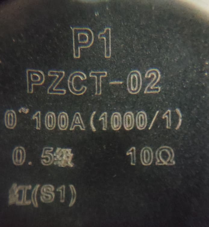
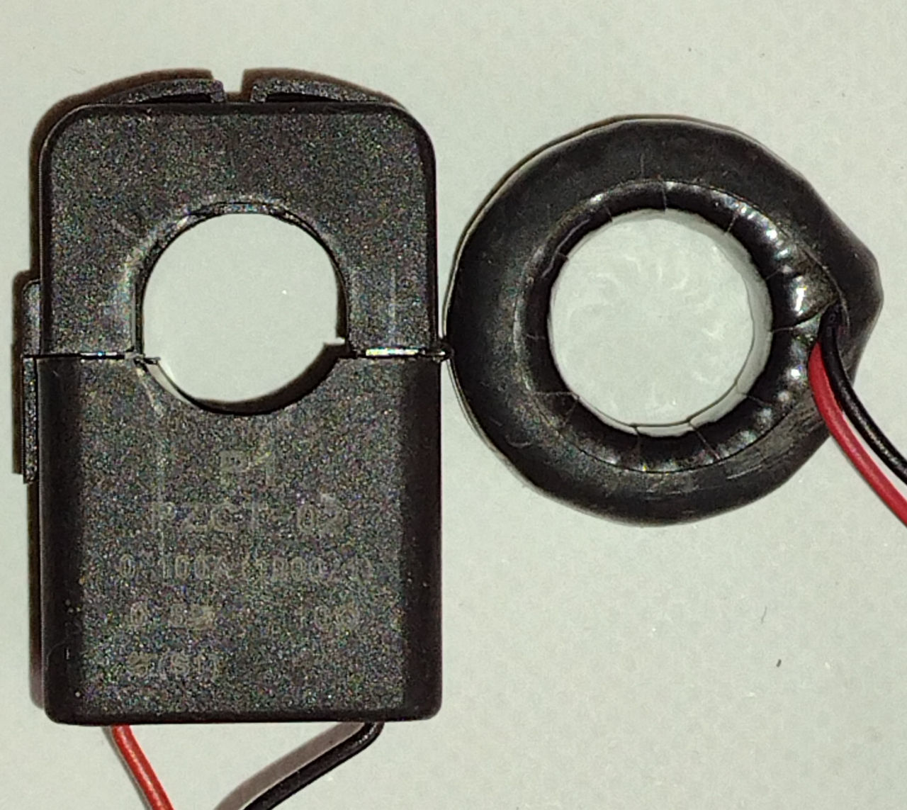
The split-core version of the CT that can be purchased with a -004T (PZCT-02) is rated at 100A:100mA.
I don’t know if the solid-core version of the CT has the same rating. I have a PZEM-004, which is a PZEM-004T with an LED display. The solid-core CT that came with it is rated at 100 Amps max, but I have no data on its secondary rating. My guess is that it’s the same, (or close) as the instrument can be purchased with either CT.
I too have a PZCT-02, which came with a PZEM-022, so it’s looking very likely that the input is 100 mA.
I read 24 mV (resolution 1 mV) at 50 A indicated (50 mA secondary current), which makes the instrument appear as a burden resistance of 0.48 Ω (±4% resolution error at least).
On that basis, the 1 A c.t. needs a parallel burden of 53.3 mΩ, so that the 1 A current shares 900 mA through the second burden, and 100 mA through the instrument, and pro rata at lower currents.
Not the most elegant solution, but what if he ran the 500A:1A CT secondary into a suitable burden,
then used the 100A:100mA CT to measure the secondary current of the 500A CT
with say, 10 turns through the wire window of the 100A:100mA CT?
This is a possibility but it will make the unit quite bulky , it there is no other option I would then rather look at the 5a as that will give a bit higher range.
Everything depends on the accuracy of that, combined with the accuracy of my estimate for the burden presented by the instrument. It’s the ratio of the two resistances that determines how the current shares. In practice, you’d need to trim the value of that to calibrate the instrument, using a known good meter for comparison.
As I pointed out, my estimate of 480 mΩ has a potential error of at least 4%.
[Edit]
And measuring again with a DSO, I got 21.2 mV @ 40 A indicated = 530 mΩ, i.e. ~10% higher.
Why bother with a burden? The c.t. will be very happy driving into an almost dead short - it’s delivering almost zero power. It could be a 100-turns coil - or as many turns as will fit and give a nice round number to multiply the reading by - say 50 turns ideally. 500 A primary current in the ‘big’ c.t will give 1 A secondary current, and 50 At from the primary winding of the ‘small’ c.t, and the instrument reads 50 A instead of 500.
It’s certainly not dependent on a home-made shunt for accuracy, only on the ratios of the c.t’s and the calibration of the instrument itself.
I have to say I am getting around with the Idea to have a secondary CT. At first I was thinking the original CT that is quite big but as @Robert.Wall noted , it can be any size ct as long as you create enough windings.
If I do go that route what impact will this have on measuring a 3 phase system? In other word using 3x PZEM-004 devices with the smaller CT’s to measure the 500 A feed.
** EDIT to avoid misleading terminology**
Your original problem is you have (or intend to have?) a c.t. with a 1 A secondary, whereas the instrument expects 100 mA to indicate 100 A (I presume). Your need is to get that 100 mA for 500 A load current. As @Bill.Thomson suggested, a 500 A : 100 mA c.t. would do it in one step, your alternative is to do it in two steps and use your 100 A c.t. as an interposing c.t., in which case your better solution would be a 500:5 primary c.t.; and then use 10 turns in the secondary winding of that to give you 50 At to indicate 50 A on the instrument using its original 100 A c.t. (And multiply the reading by 10.)
You do the same for each phase. I take it your feed is 500 A per phase, and you haven’t calculated that from a VA rating, which would be the total across all three phases?
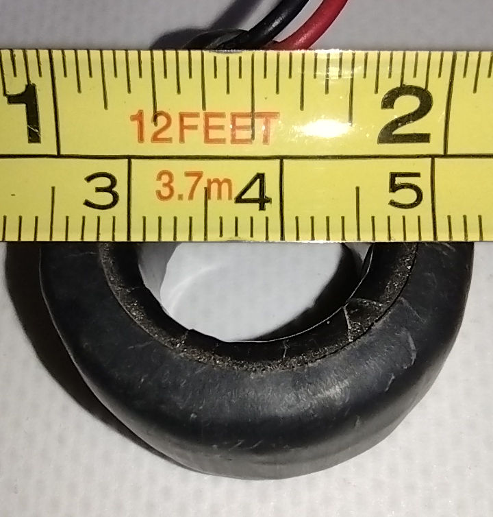
Correct , I would then use the solid core PZCT-02 ct rather than the split core ct as it would be it would be unnecessary to have a split core for the first ct.
That made me think “which will there be room for, 10 turns of wire capable of safely handling 5 Amps,
or 50 turns of wire that can safely handle 1 Amp?”
I think there’s a good chance. For 10 wires bunched carrying 5 A, it would need derating by a factor of about 2, so the cable needs rating at 10 A - that’s 1 mm² in a thermally insulated duct according to my reference material. It’s a c.t. secondary, so insulation thickness is minimal - it can be earthed.
1.5 mm² insulated wire is 2.3 mm diameter, and 10 strands of that will go easily through a PZCT-02. Drawn to scale:
My c.t. test coil is 20 turns of 0.5 mm², tightly bunched through the c.t, and it gets warm after a few minutes at 5 A. I’m not bothered, because it’s closely supervised while I’m testing c.t’s or new software. 1 mm² should be OK, I’m quite sure 1.5 mm² will be at 5 A.