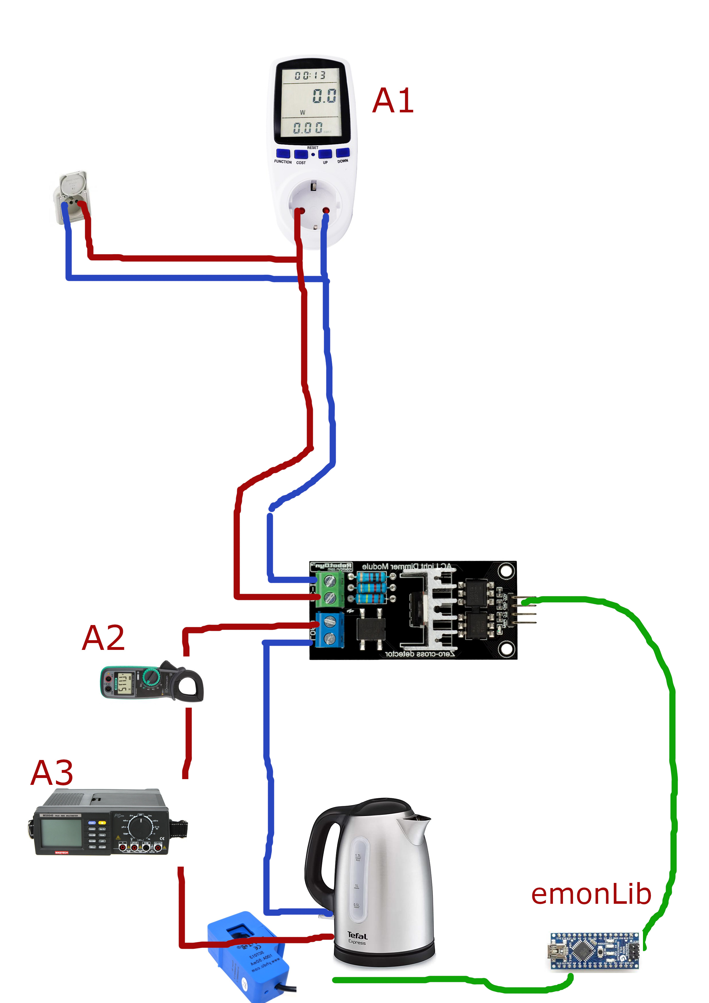
I created a prototype from Arduino to manage the self-consumption of my water heater. I use SCT006 to measure the consumption of my hot water tank. Here is the problem
when the dimmer is at 100% : the current reading is correct
when the lower the dimmer, the larger the reading error for the current.
Is there a solution ? Is it possible to read current on a triac dimmable load ?
How do you know there is a large error? What are you comparing it with?
The reason I question this is because many ammeters read the rectified average current but scale the value displayed to indicate the rms value, assuming that the shape of the wave is a pure sinusoid. If you have a phase-controlled dimmer and it is set at 50%, the triac starts to conduct half-way along the first half-cycle, turns off as the current passes through zero, and turns on again half-way along the second half-cycle. That wave is does not have the same relationship between the rectified average value and the rms value, your meter reads wrongly. The emonTx and emonPi, and anything using emonLib or emonLibCM will read the true power and the true rms current, as will an (expensive) ammeter that calls itself “true rms”. If the ammeter does not say “true rms”, then it will not show the correct rms current with a chopped-up wave.
Thank you for your answer.
If I understand what you say : all my multimeters read a wrong Irms but EmonTX or EmonPI read true Irms then using trial on load ? Is it right ?
No, I didn’t say that at all - I said they will be wrong if they are not true rms-reading, which you can find out from the instruction book or data sheet.
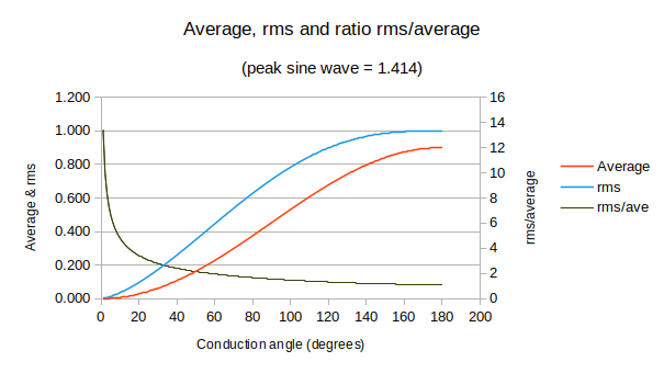
I’ve done a spreadsheet calculating the average and rms values for a triac output waveform over conduction angles of 0 - 180°.
The input sine wave amplitude is 1.414, as expected the rms value is 1.0 at 180°, the average is 0.9 and the ratio of rms to average is also as expected 1.11 (the black line). This is the factor by which a meter that measures the rectified average is scaled to show the rms value. As the conduction angle gets smaller (you turn the dimmer down), the ratio between the rms and average values changes, hence the error in the average value increases. At just 1° conduction angle, the scale factor you would need is 13.6
The rms value is the one that you are really interested in, as it represents the amount of heat going into the water.
After verification on all my multimeters are “True Rms”. However, I have a difference between them and value reported by emonLib except when wave form is complete (100% of dimmer).
With dimmer at 10% : A1,A2 and A3 are about 0,98A and emonLib 1,7A
With dimmer at 25% : A1,A2 and A3 are about 3,04A and emonLib 4,48A
With dimmer at 50% : A1,A2 and A3 are about 6,56A and emonLib 8,28A
With dimmer at 95% : A1,A2 and A3 are about 8,9A and emonLib 1,9,02A
There is also something called “crest factor”. This is the ratio of peak to rms and for my true rms multimeter, it will only read accurately when that ratio is less than or equal to 3 (up to 500 V on the voltage range, then ≤ 1.5). Your meter(s) will probably be different.
There is no such rating for emonLib, but at minimum conduction angle, there will clearly be measurement errors arising from errors in the c.t. - partly because of the way the magnetic circuit operates when the current is low. There are also likely to be errors because a transformer acts as a high-pass filter (clearly it must be because it relies on changing magnetic fields and does not work on direct current!), so I can believe that is introducing an error as it tries to restore the d.c. level between pulses.
It would be interesting to see how a Hall-effect sensor would read.
The only way that I can think to obtain the absolutely correct average current is by calorimetry - when you measure the heating effect of the current (which is of course how the rms average is defined).
I have never measured the current from a triac dimmer using an emonTx/emonLib, so I can only put forward all the things that I know about that will affect the measurements -whether they are made with that or with your meters.
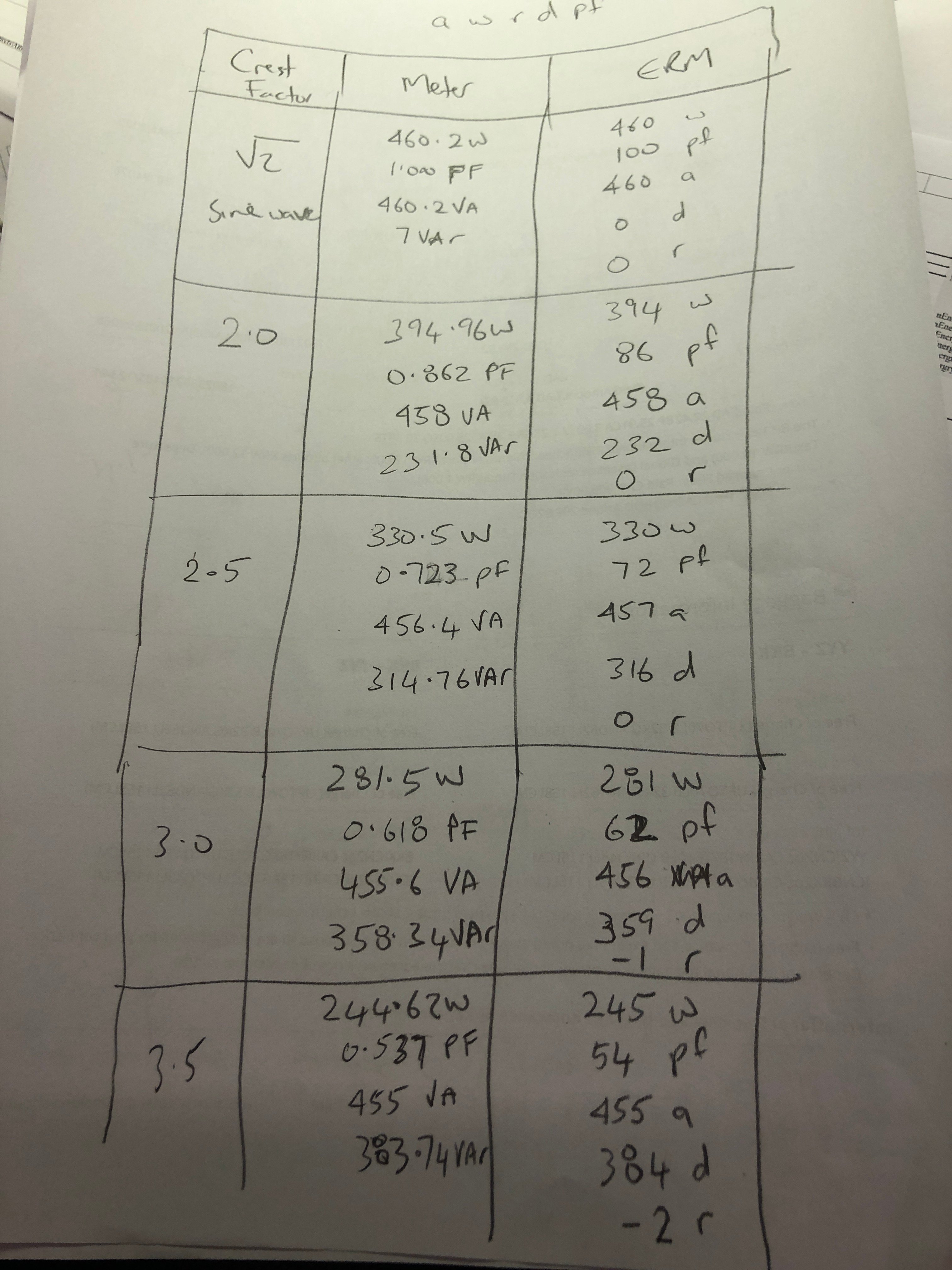
I recently had an opportunity to test my CT+energy IC based monitor at various crest factors and was impressed at how well it did. At least with the CTs I use, and the 8kHz sampling rate the energy IC uses, it got impressively close to a reference meter that had no magnetics.
I set an AC lab supply to 230V, 50Hz and a programmable AC load up in constant current mode, and tried out various crest factors… the highest being 3.5.
Then I compared the monitor results (“ERM” column) with a reference meter (“Meter” column) for real power, power factor, apparent power, distortion power, and reactive power at various crest factor settings:
I’ve since added another digit to my PF display and get a good match there too. The shape of this load is different to your dimmer, but it does at least demonstrate that some pretty nasty looking signals can be passed through a CT.