Hello,
I want to use the preinstalled Node-RED on emonPi for controlling relays.
I’m looking for fitting relays and ways to connect them. Is there somebody on the forum who’s already running a system like this?
Maybe someone could give me some tips where to start.
It would help if you describe what you wish control with the relays. There’s loads of relay boards available for the RPI, but your application will determine the most suitable hardware needed. Relay types can be controlled by radio, wifi, USB, hard-wired, etc.
Setting up node-RED and a Raspberry Pi to control relays, is not that complicated. Determining the most suitable and compatible hardware that best suits the requirements, and limitations of your application is the first step.
To Neil and in general:
The aim is to manage an energy storage. I have currents of about 16A, maybe a bit more. I’m sure theres tons of fitting relays and I’m also a bit experienced when it comes to electrical engineering.
The thing is I never worked with Raspberry Pi before and would like to know if its as easy as connecting the control circuit to the board and adjusting Node-RED.
Also I want to control which battery packs are getting loaded first, so I want to have a constant look at the voltage on several points in the system. Is there a limit to how many Volt-meters I can use, if yes is there an easy way adjust that?
I was thinking about buying an enomPi, and hard wire everything.
@Robert
As far as I see it those hats are too fragile. Theres too much current.
It also seems as if the emonPi doesn’t have many in or outputs.
@Brian
Just some switches for the load circuit. Sonoff seems not useful for me, but pretty nice for smaller things, thanks for mentioning.
I believe the EmonPi does have spare gpio outputs see: EmonPi Wiki that you could use to hardwire relays. Be aware that the Raspberry Pi has power limitations. I personally would consider using relays that are distributed and communicate with the RPi wirelessly to reduce wiring runs and to avoid having to work with the Raspberry Pi header.
I’m assuming you have some experience with Linux or it’s derivatives, if not, you may have a learning curve first. Be aware that node-RED does not come pre-installed on new EmonPi’s but it can be installed using these instructions node-RED: Running on Raspberry Pi
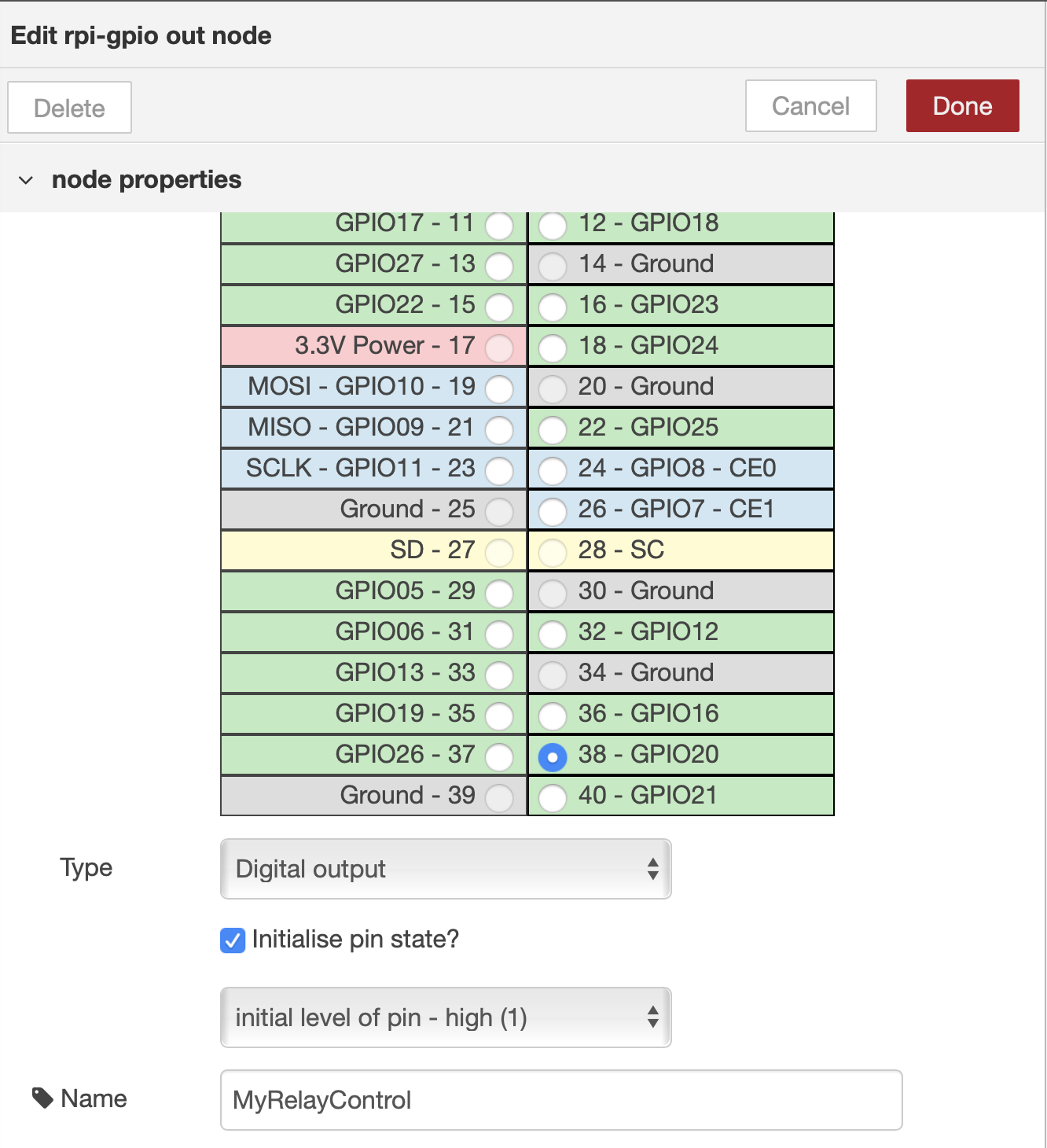
Once you have your relays installed and node-RED running, actually controlling the relays is quite simple. You can control the relays however you like by using the large array of node-RED nodes that are available. For the RPi gpio you will need something like node-red-contrib-gpio.
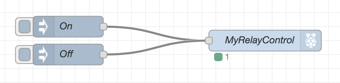
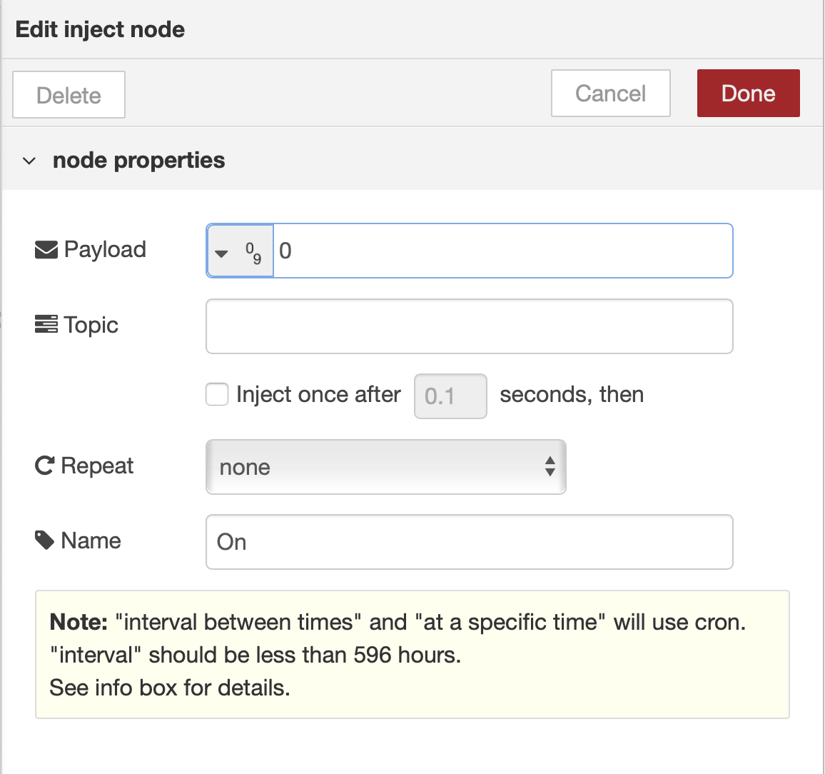
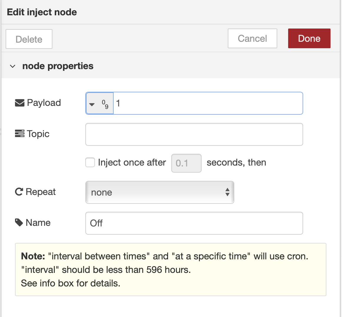
Here’s a very simple node-RED flow just to illustrate how to manually turn ON/OFF a gpio port:
Sorry, as far as I know, getting analog inputs into the RPi is not trivial, I think the Arduino is more suitable but I’m not experienced with that. I’m sure someone else here can help you with that.
Thank you very much for you detailed answer! It really helped. The screenshots show me that programming this is pretty straight forward.
As for the GPIOs, I’ve seen that they’re pretty low voltage and current, but that’s not a real problem since there are many relays for the RPi (some up to 20A).
I heard that the Arduino is better suited for that somewhere else, so I’ll read into that.
If someone is reading this and has a few basic tips or a good tutorial, feel free to post it.
Edit:
I found a way to direclty measure the voltage on the RPi. I maybe have to extend the number of GPIO ports, but that shouldn’t be a problem.
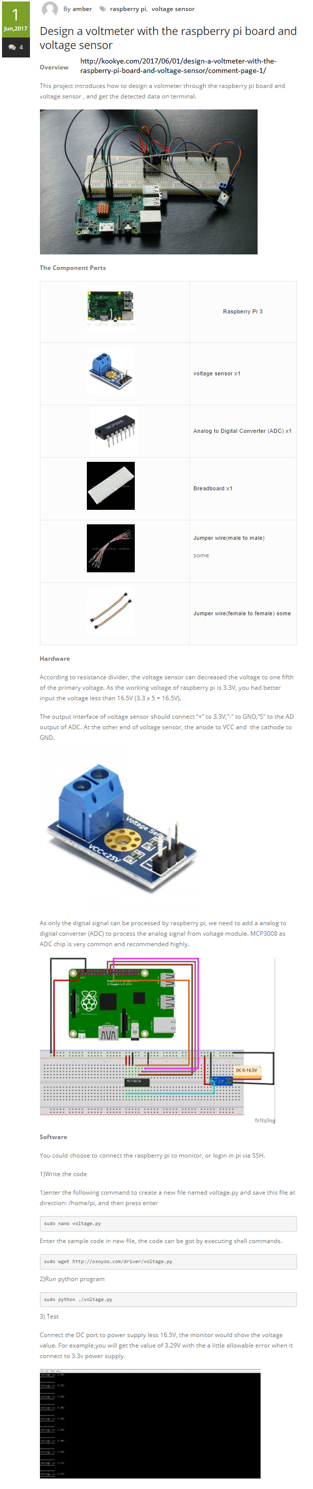
The volt meter you can buy usualy work with the voltage divider rule. As stated in the guide the voltage gets lowered to 1/5 of the one you want to measure.
Theres two restistors inside (R1=7,5 kOhm and R2=30 kOhm) in the one I found more info on and I guess they’re all the same.
I haven’t tested it but I’m sure you can just put another resistor (+ potentiometer) in series to measure any voltage you want.
Do remember that in general, and unless you can be sure that it’s safe to interconnect two systems, you must ensure that fault currents cannot flow when you make the connections and that usually means the two systems must be galvanically isolated from each other. If not, there’s a risk of damage to either or both.