USA - Dual Power Panel Installation - Electrical Code Question

I’ve been googling on this but can’t seem to find the answer that I am looking for.

I recently upgraded my service from 225A to 400A (All electric house, anticipation of electric vehicle in future, finishing basement with drywall and wanted to get it done).
As part of this, I now have 2 power panels in parallel.

I had an emonesp working really well, but now I’ll need a set up that can accomidate two sets of current transducers to gather data from both my panels.

My question is, can I run both sets of CTs to a single junction box that has knockouts connecting both panels or would this be a violation of electrical code? I can sketch up a diagram if this is confusing.

I presume you don’t have access to the service entry cables before they split to feed the two panels?

My colleague @Bill.Thomson knows more about installation practice in the USA, but my view is, the c.t. secondary wiring is in my language “Separated Extra Low Voltage” instrumentation and would not, provided it is segregated from the 120 V wiring by a physical barrier, be covered by a code of practice.

The NEC covers both high and low voltage wiring.
The most common “code violation” is running both categories of wiring in the same conduit.

On top of that there are likely to be state and local regs that should be adhered to.
The folks in your area who issue building permits and perform construction inspections should be
able to tell you, or at least direct you to somone who can.

just curious why the switch to 400amp service for an electric car are anticipating buying a a fleet of them :wink: – I have an all electric house ( +1200Sqf) but I greened the heating and cooling. but the highest amperage i reach say on Christmas day cooking 13 course Christmas dinner on a -40c day is normally <60amps ( <13kw --normal average peak is <7 kw). and I have an electric vehicle on level 1 charger.

I think maybe they should design electric car charger to be a bit more smarter and adaptive one that can look at the over all grid usage and adjust charge rate to match the service panel or intelligent AI version that looks at your normal usage and adjust to your household patterns - because 90% of the time I doubt you were using 10% of your previous 225 amp service … and level 2 charger are 16 - 40 amps and they are generally charging during off peak hours. If I had a level 2 charger that is what I would do if I found that my current 100 amp service panel was not enough builds an AI level 2 charger that was adaptive .

Hey friends, thank you for the replies!

I contacted my town and asked a building inspector about this and he was confused as to what I was installing and why I would want such a device, hence why I asked here before continuing that conversation.

My house was built in the 80’s with a 225 amp meter and main breaker. Panel had 42 slots all taken and 10 tandem breakers already installed. The house is probably ~2300 sq ft and completely electric. Two air/air heat pumps & air handlers, water heater, oven, clothes dryer, microwave, space heaters, etc; In February I would be pushing 130+ amps.

I am finishing my basement with drywall and anticipate in 5 - 10 years possibly owning an electric car. A car charging circuit can draw 40 - 50 amps and maybe even more in the future, who knows, so I wanted to put in a sub panel in the garage to be able to easily add a car charging outlet in the future when that happens, and not have to tear out the drywall in my basement to run the wire.

So 130+ amps currently max load + electric car charging brings me to 180+ amps and 80% capacity on a 35 year old Culter Hammer breaker; Adding ~10 circuits to an existing maxed out panel; The panel was a complete mess and I would have had to build out a soffit in the basement to accommodate the wires. You can see how this is escalating.

I called the utility to see about an upgrade and it turns out the in place wiring is already able to support a 400 amp service (320 amps realistically). People tried to explain that a 400 amp service is really a 320 amp service and I didn’t understand.

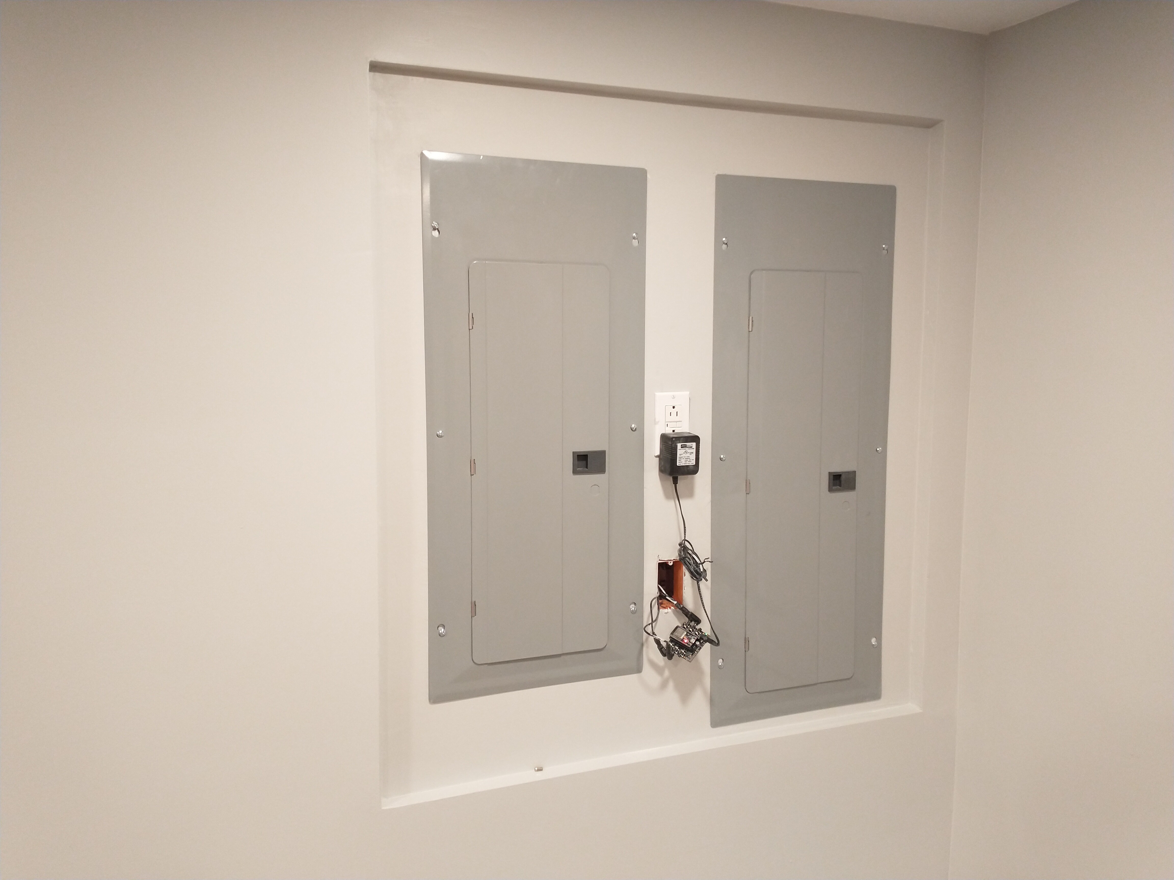
I called a few electricians to see what they thought and got a few ideas, but the best was to install 2 new panels on a split feed, reorganize the wires and run a 100 amp sub panel (doing the work already, might as well upsize to 100 amps) into the garage. I got a really good price from one electrician so it made sense to hire them and do it.

Now I want to be able to meter my usage internally!

Old Panel: https://photos.app.goo.gl/KYvRz24vroEVqU4K9
New Panels: https://photos.app.goo.gl/TChwhXvaZdvK7DXr7

Unless your energy provider upgraded the transformer that feeds your house, your upgrade
isn’t going to give you an increase in continuously available current.

This will explain why:

The two are different.

The service rating is an often misunderstood “number.”
The number itself refers to the max rating of the weakest link from the transformer to the
load center. (circuit breaker panel) That includes the Service Enrtance Wires, meter and meter base as well as the load center itself.

Can you upload your photos here instead of somewhere else, please. If they get taken off that 3rd party site, this thread becomes largely useless to anyone with the same problem reading it in the future.

That sounds like you ended up talking to the wrong person. As your electrician must be conversant with your local regulations, I’d ask him. Maybe the inspector didn’t appreciate the the c.t’s only work at about 1 V, and are isolated from the supply and the insulation is good to 600 V or more.

Here’s how it ended up. I’ll post a final final picture when it’s final final.

CTs on each feed coming out through holes in the power panels with grommets into a LV gang. I will 3D print a mount for my circuitsetup board that attaches to the gang box. Mains run from right box on its own 15A breaker to a GFCI recepticle.