OK. Thanks for the clarification. That makes it much easier to help you.
You mentioned “two-leg” circuits. For your 240 Volt loads, you can use a single CT if you’re OK with a
small amount of error caused by any 120 Volt load that’s part of said 240 Volt device. e.g. the electronics and motor in a clothes dryer are typically 120 Volt devices as opposed to the heating
element which is a 240 Volt device and represents the largest part of the total load. A CT on one
of the hot legs will enable you to monitor the 240 Volt load, but not the 120 Volt load, because its return path is via the neutral leg.
If you want to monitor 120 Volt circuits, you’ll need one CT for each circuit.
So your final “channel” count will be determined by the number of 240 Volt and 120 Volt circuits you
want to monitor and whether or not you’re OK with ignoring small errors monitoring your 240 Volt loads with a single CT. If not, you’ll need two CTs for each 240 Volt circuit you want minimal measurement errors on.
This isn’t great advice for US users, because nearly all appliances, equipment and lighting are 120V and there can be a huge difference between usage on the two sides of the 240V circuit. One of the reasons I’m doing this is to make sure things stay more or less balanced. Probably won’t make a difference but if my usage is higher than I anticipated I might wind up overloading one side.
Your load center (circuit breaker box) is physically constructed to do that for you.
The bus bars are built such that the even numbered breakers are on one leg and the odd numbered
breakers are on the other leg. When your house was wired, the electrician ran the wiring in a manner
that prevents, or at least, helps to avoid piling all or most of the loads on one leg. All US residential
electrical service is like that. The actual load difference between Leg1 and Leg2 isn’t so large as to be
a problem. If you drew too much current, you’d trip a circuit breaker. That’ll happen regardless of
the load “balance.”
You’re limited in the total amount of current you can draw continuously from the transformer that supplies your house. Most houses in the US are fed with a 15kVA or 25kVA transformer. The total continuously available current from a 15kVA pot is 62.5 Amps and from a 25kVA pot is 104 Amps.
On top of that you have to “share” that supply with one to three neighbors. How can that work,
you ask? The same principle is used in your load center. If you add up all of the numbers on each
circuit breaker in your LC, you’ll find they exceed the rating of the main breaker. Possibly by quite
a large amount. That “works” because you don’t (normally!) have all or most of your electrical loads powered on at the same time. The same is true with your neighbors that share the the transformer feeding your and their houses. It’s actually very rare that all or most of you would have all or most of your electrical loads powered on at the same time.
Yup. I’m the “electrician” BTW, wiring it up myself. And it’s not likely, but it happens. And even if it’s not enough to trip one side, it can easily be enough to throw usage measurement off by a large amount. I’ll spend the extra $ to get an accurate measurement.
It’s a center-tapped transformer, and it’s possible to overheat one of the windings before the other. In any case, by “overload” I mean trip the breaker; and the breakers don’t add the current usage from both sides and average them, they measure them separately. Going over 100A usage on either side of a 100A two-pole combined breaker will trip the breaker.
Aaaand I’m getting confused, and being confusing. Sorry. I meant this device. Which, since I probably won’t be using the RF interface, I should probably just use pain Pis.
Thank you! I’ll keep them in mind. I was planning on buying the full devices and mounting them on a board.
Your kWh meter measures both legs, so whether balanced or not, there’s no inaccuracy.
At least not any that matters. As Robert has said, the kWh meter is by definition 100% accurate even if it’s not! as it’s the source of the numbers used to bill the customer.
IOW, is the electric company going to let any of us get away with not getting billed for what we use?
The pole mounted fuse in the fuse door will handle that situation.
A two-pole breaker means a 240 Volt circuit, which means the same current is flowing in both poles
offset by any current that might be flowing in the neutral leg. e.g. a clothes dryer. The electronics
and motor will use a small (compared to the heating element) amount of current, so there will be
a small difference in the amount of current through the two legs.
On a “pure” 240 Volt load, i.e. no 120 Volt devices on that circuit, the current flowing in both legs
will be the same.
I suspect your revenue meter is basically two 120V watt-meters, in much the same was as our three phase meters are three 240V watt-meters. It sounds like @TheSHAD0W is keen to mimic that as closely as possible although it wasn’t clear to me John whether you plan measuring each leg’s V?
True, and at first blush that seems like a waste of a CT as you’ve effectively got two CTs wrapped around the exact same cable. Imagine the situation though where one leg is at 130V and the other at 110V (set aside how improbable that is - I’m just talking theory here). If you do away with one of those CTs then which V are you going to multiply the remaining CT against? It’s tempting to say well the two Vs add up to 240V so just multiply it by that but AC watt-meters don’t work on RMS values, they’re looking at hundreds of instantaneous V samples throughout the cycle so you’re going to have to choose one V or the other (or do some real time instantaneous combination of the two Vs). I think if you want to do away with the “redundant” CT for a pure 240V load you’re going to need a third watt-meter (240V) connected across the two legs (assuming you’re trying to measure things the way your revenue meter does - if you’re happy to compromise on that then there are lots of short cuts available).
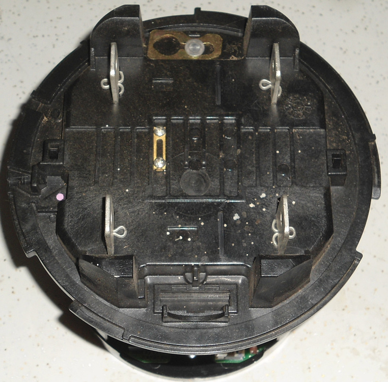
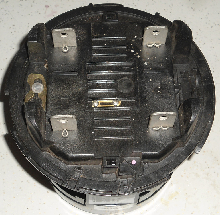
Two contacts connect to the source, the other two to the load center. (circuit breaker panel)
Believe it or not, that happens more often than one would think. It tends to be fairly short lived though
as it manifests itself in lights that either flicker between brightness levels, or lights that are quite a bit
brighter in one part of a house and at normal brightness in the rest of the building. The occupant of
said building usually wastes little or no time in contacting the electrical utility to report the problem, if for no other reason that it can be really aggravating.
A poor bond to the neutral at the service entrance will make the lights in the entire building do the brightness “dance” whereas a bad neutral bond in a load center will cause the problem to happen on the circuit the neutral belongs to. I’ve a friend who is the electrical superintendent of the city he lives in and he’s told me they replace faulty service entrance neutral bonds about once every one to two months.
But, the neutral does get used. Just not at the meter.
Or more correctly, not through the meter.
I added a couple of pics to my post that show the contact arrangement.
Thanks. So there are two watt-meters in there they just don’t have reference to Neutral. I think that might be Fig3a in this excellent description.
So I think what I wrote above stands. If you want to exactly mimic your revenue meter for the measurement of a pure 240V load you need two CTs, or you could measure it with a single CT and a V across both legs - since pure means there’s nothing traveling down N.
Although I’m struggling on this cold winter’s morning, to get my head around how Fig3a performs when that N is a long way off the mid-point… more coffee might be required.
Evidently that’s how the electrical utility sees it.
But, if the load is a “pure” 240 Volt device, you only need one meter.
As Robert has often said "classical theory says you need one less wattmeter than the number of wires you have. Since there are only two wires with a pure 240 V load, only one is needed.
The utility has to take into account the 120 V loads, which means three wires (in total) and
hence two meters.
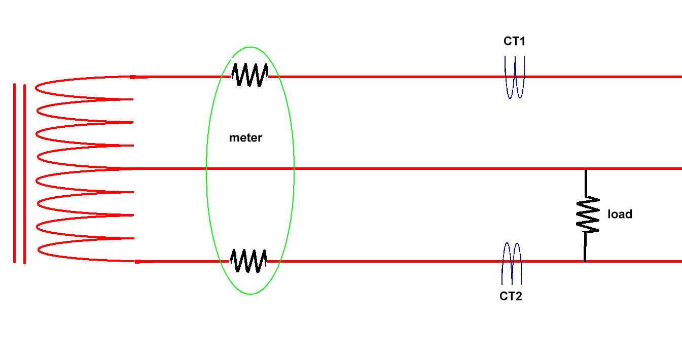
Yup, as shown, having only CT1 on the circuit will miss this load, while the meter, monitoring both sides, will catch it. You’d need CT2 in order to get a complete reading. And while circuits will be staggered so that they roughly balance out, if a constant load, which is what will have the greatest effect on the bill, happens to be on the side the CT isn’t, you’ll miss that usage.
Regarding #2, you could get a European adapter and wire up a 240V circuit for it easily enough.
Regarding #1, yeah, there’s often a few volts difference between the two legs depending on load, and that can introduce inaccuracies. In my particular case, since I’m using multiple emonTx devices in even quantities, I can have them monitor separate legs of the service and hand them voltages from those specific legs.
So your final “channel” count will be determined by the number of 240 Volt and 120 Volt circuits you want to monitor and whether or not you’re OK with ignoring small errors monitoring your 240 Volt loads with a single CT. If not, you’ll need two CTs for each 240 Volt circuit you want minimal measurement errors on.
as the above drawing illustrates exactly what I was trying to convey.
I don’t think anyone has ever disputed that. If you’re talking of monitoring the total consumption, everyone here agrees that you need to measure the current in both legs.
If you’re measuring one 120 V circuit, we agree you need only one c.t for that.
If you’re measuring one pure 240 V circuit with a two-wire connection, I think we agree that you need only one c.t for that.
Where I think there is some debate is when considering the inaccuracy when measuring a 240 V appliance that has a 3-wire connection. The assumption that means only one c.t. is needed is that the neutral wire carries an insignificant current compared to the two line conductors (‘hot’ wires), because that is the current which is drawn by the control electronics or similar, and it’s much smaller than the normal load.
If the assumption is valid, the error from using just one c.t. is insignificant. If it’s not, the error will be significant and to remove the error, two c.t’s are needed.
Well, the answer is simple IMO; buy one CT and stick it on the neutral wire first. If you see more than that insignificant usage, well, you’ll need to pick up a 2nd one!
Oh! Would it be a good idea to use Rpi 4s for running emonHub? Or would it be overkill, or cause problems?