Hey all. First time poster.
I’ve read through all the installation procedures for making an arduino version of the openenergymonitor using the emonLib for the Arduino. I have gotten 2 SCT-013-000 probes and have them working properly.
Now I want to measure the voltage of the mains so that I can get an accurate read on the wattage usage. This is where I am super confused. In the Guide is talks about using a wall wart. I have plenty of these little things laying around. However, I am completely confused as to how to use one of these things to measure voltage. In the Guide, the schematic shows a transformer, but talks about the wall wart. Do I take the transformer out of the wall wart and use the resistors mentioned in the article, or do I connect up directly the output leads of the wall wart?
I’ve done searches here in the forum, and on Google. And all I get back is people who are still clueless, or pages where using the wall wart to power to the arduino, or to use it as a cheap ac->dc converter for other projects. I can’t find to use it as a metering device.
Any help is greatly appreciated.
I think you might (finally?) have come to the right place.
Firstly, what you want is a low voltage (i.e. safe to handle) replica of your mains voltage, i.e. a.c. Your Arduino requires a d.c. supply. Those are different things, so you cannot easily use the same for both. Keep your 9 V d.c. (or whatever it is you use) for powering the Arduino, and use a separate device for monitoring the mains voltage. In our on-line shop, we can sell you an a.c. adapter that is known to be satisfactory. But you can if you wish use any small isolating transformer that gives more than a couple of volts output. Unless the voltage is between 1.0 V and 1.5 V, then you will need a pair of resistors to reduce the voltage into your Arduino down to the correct level, and you will need the matched pair of resistors and capacitor (like you used with your c.t. inputs) to bias that input correctly.
If you have a plug-in d.c. power pack that you can open up, then you can probably re-purpose that. You’ll need to remove the rectifier and smoothing components and measure the voltage, then calculate the resistors you need to give the correct voltage for the Arduino input. If you’re unsure, post a picture of the internals of the unit you’re modifying, and I’ll try to tell you what you need to do.
Thanks Robert
Yes, the arduino will be powered by a separate wall wart. I was going to use old cell phone chargers to use as the sensors.
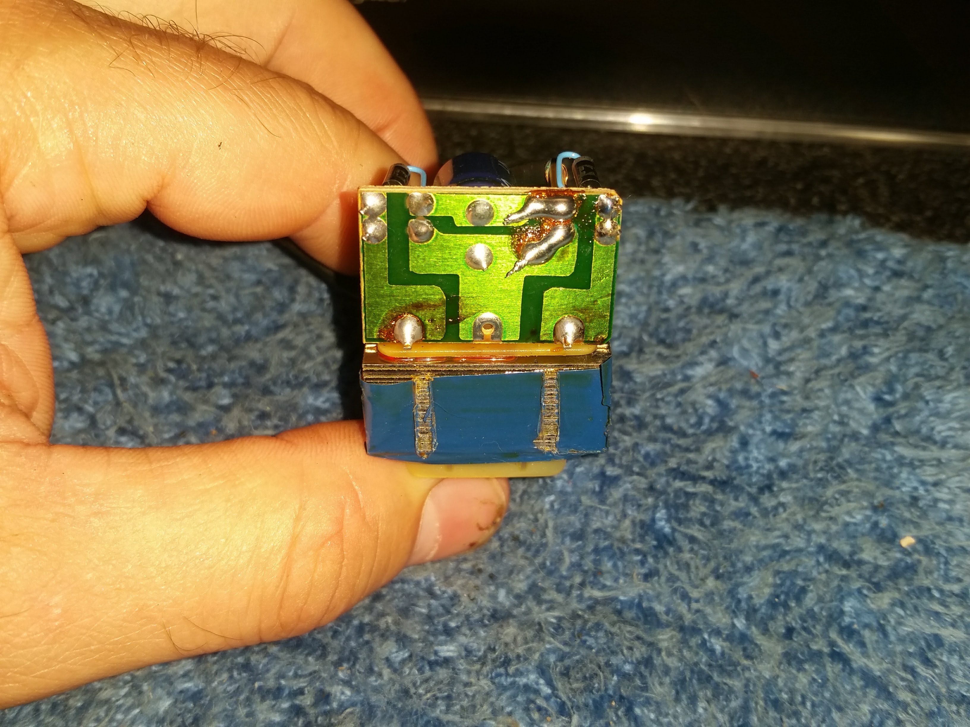
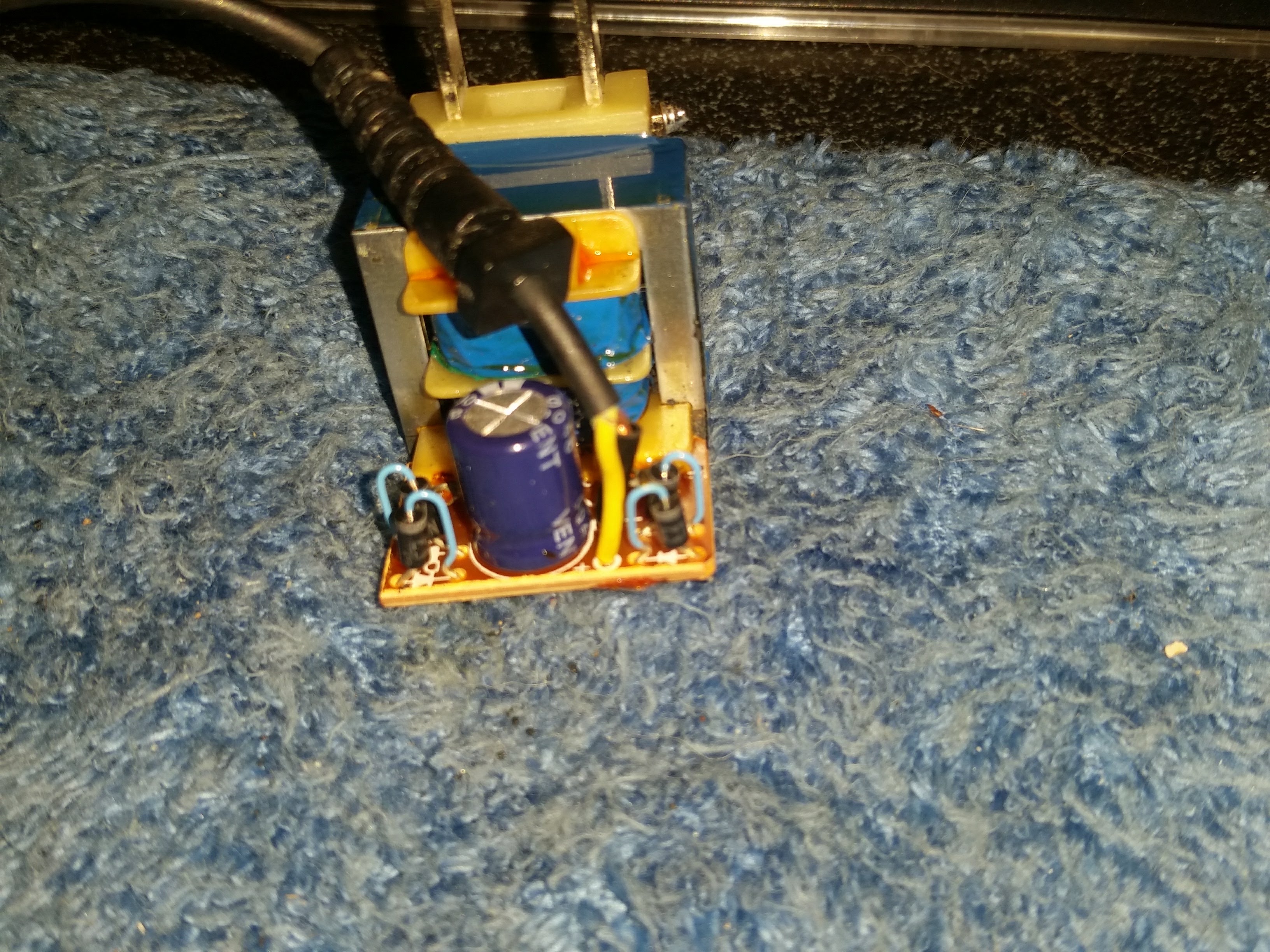
Hahah, was just looking out for some, and found some really old ones. I was originally going to use the ones with the micro-USB cable on them. But decided to look around my scrap pile and found one that puts out 4V @ 200mA. Upon taking it apart, it has only 4 diodes, a cap, and transformer. The USB ones had a lot more in them than this. So will this work better than the others?
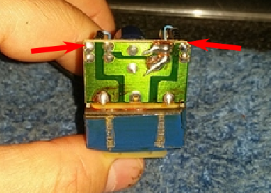
The USB ones with lots of components would probably not have been suitable - they are likely to be switched-mode power supplies. The one you’ve chosen looks to be OK. You need to move the output cable from where it is, and solder onto the two outer copper pads (arrowed). You can if you wish remove the diodes and capacitor, but they shouldn’t do any harm to be left there. But if you do remove the diodes, you might find the holes useful.
Which way round you connect the wires will matter eventually, because it will determine whether real power is positive or negative. Our convention is it’s positive when importing. If the adapter can be plugged in either way round, then that’s equivalent to swapping the wires over, or putting a minus sign in the maths, so there’s no need to worry which way round they go.
Next, you need to measure the mains voltage and the voltage on the output wire, so that I can calculate the values of the resistors you need and the calibration coefficient.
Ok, kewls, thanks
Mains voltage is anywhere between 115-125V. Sometimes it will drop to about 108V, depending on the loads at the time. Altho, a lot of this wide range of fluctuations will probably go away soon. They will be upgrading the wiring, transformers, and line voltage on the power transmissions lines next year (like, next month next year )
However, to do the math now, the readings are:
Mains: 117.9V
Output: 6.2V unLoaded
Primary: 632 Ohm
Secondary: 4 Ohm
The Ohm readings where with my meter set at 2000.
Officially, your supply is 120 V ± 5%, so we’ll design for 126 V maximum. The maximum input voltage of your Arduino is 5 V peak-peak, but we need to subtract allowances for the d.c. supply being low and resistor tolerances. So I’ll aim for not more than 1.6 V rms at the Arduino input.
At 126 V, your transformer output will be 6.63 V, and if I want to keep R1 as 10 kΩ, then R2 must be not less than 31.4 kΩ. 33 kΩ is the next standard value so that will do nicely, 39 kΩ would also be OK. You don’t need to be too exact with the voltage, because it varies over a very limited range (compared to the current) and there’s plenty of leeway. If you’ve got two resistors in roughly the same ratio with a total value anywhere between 1kΩ and 100 kΩ, they would be OK. (And R3 & R4 can be any value, as long as they are equal, from about 10 kΩ up to 470 kΩ - we only use 470 kΩ to keep the current down when using batteries.)
The resistors ideally want to be 1% tolerance, metal film. 0.1 W is plenty big enough, though 0.2 W, 0.25 or 0.3 W are more readily available.
The calibration coefficient for emonLib is the voltage at the mains that would give you exactly 1 V at the Arduino input, so working backwards through R1, R2 and the transformer, that comes to
1 V × (33 + 10) ÷ 10 × 117.9 ÷ 6.2 = 81.77
The resistors Transformer
This is for R2 = 33 kΩ. You’ll need to recalculate that if you choose different resistor values, and you’ll need to adjust it anyway because of the component tolerances (in R1, R2 and the Arduino’s voltage reference).
Kewls, thanks. I’ll get back to ya when I put those bits in later on.
I appreciate the help. The using of the wall wart was confusing because I couldn’t find anywhere (though not knowing the proper search term(s) doesn’t help) on how to use one. I thought it was using the transformer directly; however, when I took another one apart and hooked the transformer without any loads or what not, I got big sparks. So not sure what I did wrong.
At least this one works as intended. Now I gotta get a second one and pull it apart and do the mods.
We never use that term, always “a.c. adapter” or “a.c. - a.c adapter”, and they are pretty rare beasts. The most common sort nowadays is the USB 5 V d.c. phone charger, the next most common is the one you’ve re-purposed, which had an unregulated d.c. output. We need a.c. because as well as measuring the amplitude of the voltage, it’s being used as a reference to detect the phase of the current, hence the direction of power. If you need the details, there’s plenty of reading in the ‘Learn’ section.
So, another question with this. I want to wire up two of these, so I can see true voltages on both Hots. I know on the 120V side they can share a wire, the Neutral. But I wonder on the reading side, can they share a common lead? Just trying to reduce the clutter on the pcb board on the inputs.
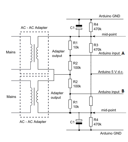
They can, but not like that. Look carefully at what you’ve drawn, you’re actually trying to parallel the two transformers’ secondary windings, because the mid-point is supposed to be a stable fixed voltage that’s a ground to a.c. by virtue of the electrolytic capacitor C1.
If you want to common things and simplify the pcb, then forget the individual bias resistors and capacitors C1, R3 & R4, and use a single op.amp. to provide the bias supply. See Learn | OpenEnergyMonitor
All inputs share the common bias supply (labelled “mid-point”), so you connect the v.t. so that the voltage you’re measuring - across the 10 kΩ - connects to the mid-point and the Arduino input for both legs of your voltage, and for the c.t. inputs it’s the burden resistor with the c.t. in parallel that connects likewise to the mid-point and the Arduino input in each case.
Thanks for the help. I got it all wired up and working
I did have one issue. I connected the analog pin to the the outside of R1, instead of between R1 and R2. Unfortunately, I killed the nano. At least they are cheap.
Dialing in the adjustment took a little while. I had to wait till morning as the mains voltage was fluctuating too much. As I mentioned earlier, next year the power company is replacing lines/transformers. With all the XMas lights and what not going on during the evening, the voltage getting to the house was suffering.
This morning was a lot easier. However, I think my DMM is in need of calibrating as I set my other DMM next to it and it was reading about .3V AC difference than the other one. So, now I gotta figure out which one is correct, or if they are both off. But that’s a different task. At least the voltage meter is working now
In the pic on the right, the bottom terminals are for the voltage sensor. The two on the top are the SCT connections.