Neither commands work.
Just wondering if anyone has any suggestions?
Thx.
Result from avrdude is…
avrdude: Version 7.3
         Copyright the AVRDUDE authors;
         see https://github.com/avrdudes/avrdude/blob/main/AUTHORS

         System wide configuration file is /opt/local/etc/avrdude.conf
         User configuration file is /Users/dr/.avrduderc
         User configuration file does not exist or is not a regular file, skipping

         Using port            : /dev/cu.wchusbserial10
         Using programmer      : jtag2updi
         Programmer baud rate  : 115200
avrdude jtagmkII_getsync() error: bad response to sign-on command: Unknown JTAG ICE mkII result code 0x01
avrdude main() error: unable to open port /dev/cu.wchusbserial10 for programmer jtag2updi
Possible candidate serial ports are:
  -P /dev/cu.Bluetooth-Incoming-Port
  -P /dev/cu.debug-console
  -P /dev/cu.OpenComm2byShokz
  -P /dev/cu.usbserial-10 (via ch340 serial adapter)
  -P /dev/cu.wchusbserial10 (via ch340 serial adapter)
Note that above ports might not be connected to a target board or an AVR programmer.
Also note there may be other direct serial ports not listed above.

avrdude done.  Thank you.
Hi @zzzdgr - you shouldn’t need sudo to run on the Mac, give it a try without. You might also be able to use the Arduino IDE. I’ve seen a few issues referencing these AliExpress UPDI Friend adaptors.
Do you have the WCH specific USB serial drivers? Worth making sure - available from WCH website. I struggled for days with a similar situation - those chips don’t work without them, whatever it looks like. And I use a Mac.
I had the exact same issue when trying to program attiny using updi friend. The solution is to bypass R16 resistor on the board. This is 470ohm resistor on the reset line, for some reason updi friend is unable to correctly communicate with the chip with that resistor present. You can either completely remove it and put a blob of solder in it’s place or bypass it by placing a piece of wire between both resistor pads during programming, a bit tricky but should do the job.
Wow. well that certainly comes as a surprise. I have used the macro on the phone to see the board and could not find the label, or the ohm value on any resistor chips. Do you know where there is detail of this? Or can you send me a picture of your board modified so i know which one to address?
thanks.
Hi. I removed r16 and jumped it with a blob of solder. Still the same. When I issue the command the UPDI friend blinks a red light. So I assume the command is getting there, just not reaching the attiny.
Any other ideas?
From your initial post I can see you are using Mac and avrdude to do the programming, I’m using linux and a python program called pymcuprog which can be installed using pip3 like so:
pip3 install pymcuprog
then the way I programmed my chip was using this command:
I believe this should work the same on mac so maybe give it a try, also maybe double check the paths from the pins you connect UPDI friend to the pads on the attiny1416 to make sure there is no faulty path. You only need to check three of them:
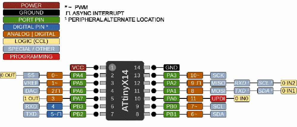
VCC (+5V) goes to pin 1 on the chip
GND goes to pin 14
and Reset line goes to pin 10 on the chip (UPDI)
also double check the connector/cables on UPDI Friend to make sure all is connected correctly and there is a direct path from the pad on UPDI Friend up to attiny1416 relevant pad. I hope this helps as I was able to program my chip this way.
This R16 470ohm resistor was not the first one I had to remove to program the chip via UPDI Friend, it was a different project with atmega4809 chip but the issue was exactly the same so at least in my situation removing or bypassing that resistor has helped me twice already. Please let me know if any of this made any difference. Also I need to mention that I bought my UPDI Friend from thepihut.com
Thanks for taking the time to put the image in for pinout. I sat down and tried this again. magnifying glass out looking for any issues with tracks or soldering. I started from one end to the other with the multimeter. pin on the attiny1614 to the updi friend pinout to ensure connectivity making sure there were no bad clips or wires. this was all ok. I tried the command again and same negative result.
So I read through things again, noting your command line using the python program. what caught my eye was “uart”. I opened chatgpt and entered the error command I received along with the chip and that I was on mac. i got back almost the same command except with “serialupdi”.
I programmed with the serialupdi. I did this on the board where I removed the r16. I tried on another board that still had the r16 but didn’t work. I took the + and - wires of the multimeter, took them out of the multimeter, jumped them together so I had a wire with 2 pointy ends! Holding the points on each end of r16 and I was able to program the second one.