I’m Trying find a serial connection out of PZEM-022. It’s a relatively cheap energy meter and being able to connect it to the outside world will be really great.
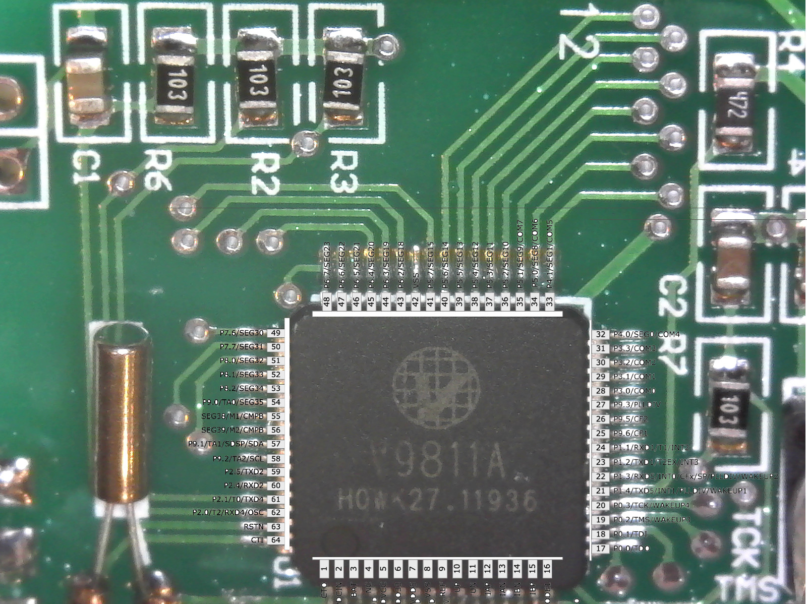
The unit utilizes a Vangotech V9811A chip (DS Here) that show having 4 UART connections as well as I2C channel on pins 57 (SDA) and 58 (SCL). I was able to solder some wires on those pins but not able to pick anything. The data sheet lists triggering some register, and guessing this needs to be in the programming of the chip, i’m trying to understand if there’s another path?
Just be aware that the processor almost certainly has a galvanic connection to the mains, so any connection you make to its pins should pass through an isolator before you hook them up to anything you can touch (Arduinos, laptops etc.).
I just hooked it up to a logic analyzer to see if I can pick anything up, you think it will still affect trying to see if there’s any output? Any suggestion on how can isolate?
Thank you!
I did look there and it appears it the PZEM-014/016 have a dedicated modbus output that is possible to tap. Looking through the documentation and the discussion, looks like PZEM-014 or 016 uses The 99811D chip from the same company and if I understand correctly, the modbus signal comes from TX2/RX2 on that chip. I’ve tried the same pins on the 9811A (59/60) and I’m still not able to see anything. I think about trying each one of the UART pins.
The fact that you have to ask worries me. I don’t want to hurt your feelings, but if you don’t know what you are doing when you are working on equipment that is, or could be, live to mains voltages, then you’re putting yourself in serious danger.
The very least you can do is get a 120 V : 120 V safety isolating transformer that is specifically designed for the purpose, and power your PZEM-022 from that. It still will NOT prevent you from getting a shock if you touch both sides of the 120 V at the same time, but it will go a long way towards reducing the risk to you or anything you connect to the PZEM that also happens to be earthed (grounded to you).
If you connected the analyser input to 120 V, and it was earthed, it’s quite possible that you’ve damaged or destroyed the input of your logic analyser.
Indeed. Even the Neutral → Earth currents are more than enough to fry your inputs long before the earth leakage breaker trips.
I think you’re confusing the datasheet for the IC they’ve used with the datasheet for the meter they’ve built. That IC is pretty much a general purpose processor with some energy monitoring thrown in. Like the AVR processor in an Arduino, each pin can be used for a multitude of different purposes depending on the meter designer’s needs. In order for you to find data on the I2C or uart pins, the firmware writer would have to have configured those pins for that purpose and then written some code to output data on those pins. My guess is they’d only do that if there was something already connected to those pins (like the isolated serial interface you find on their other products).
Ohh. You talking about AC mains
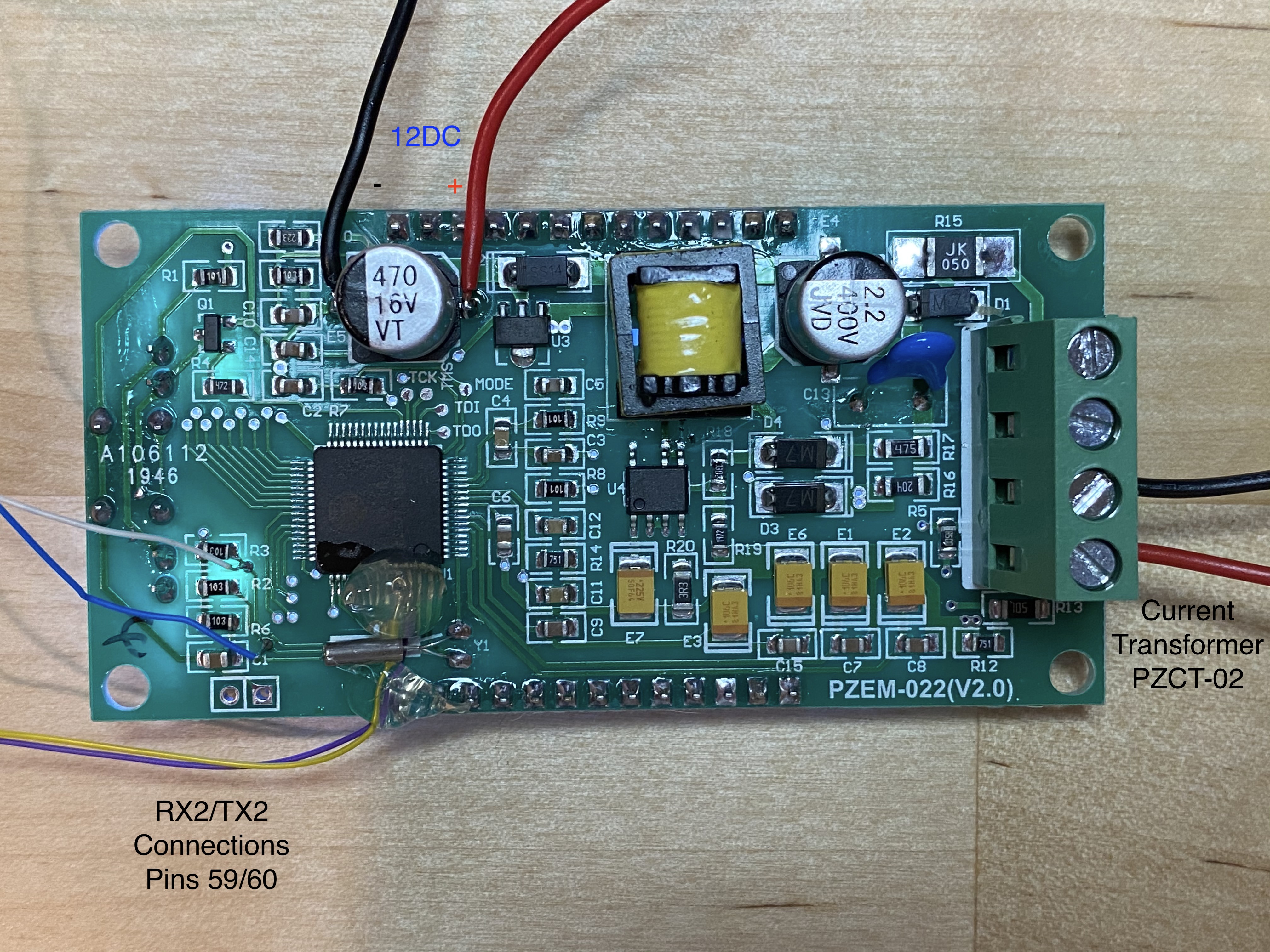
The device is not powered by AC mains while one testing. I’m using a 12VDC power supply at one of the capacitors as described in one of the posts I’ve seen for the PZEM-004. I’m able to do the testing while on a DC power supply. Sorry about misunderstanding. I’ll share a picture of the board
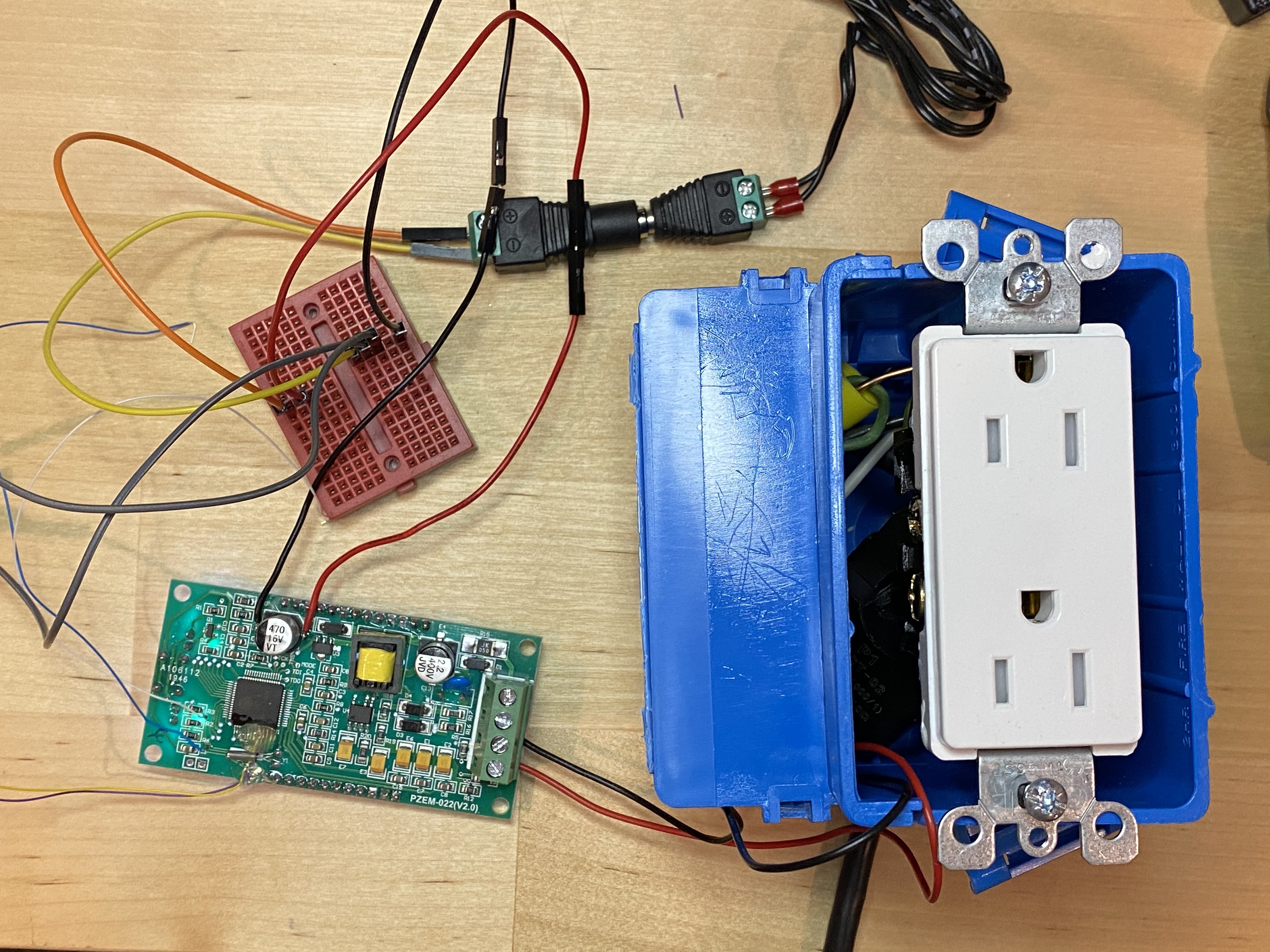
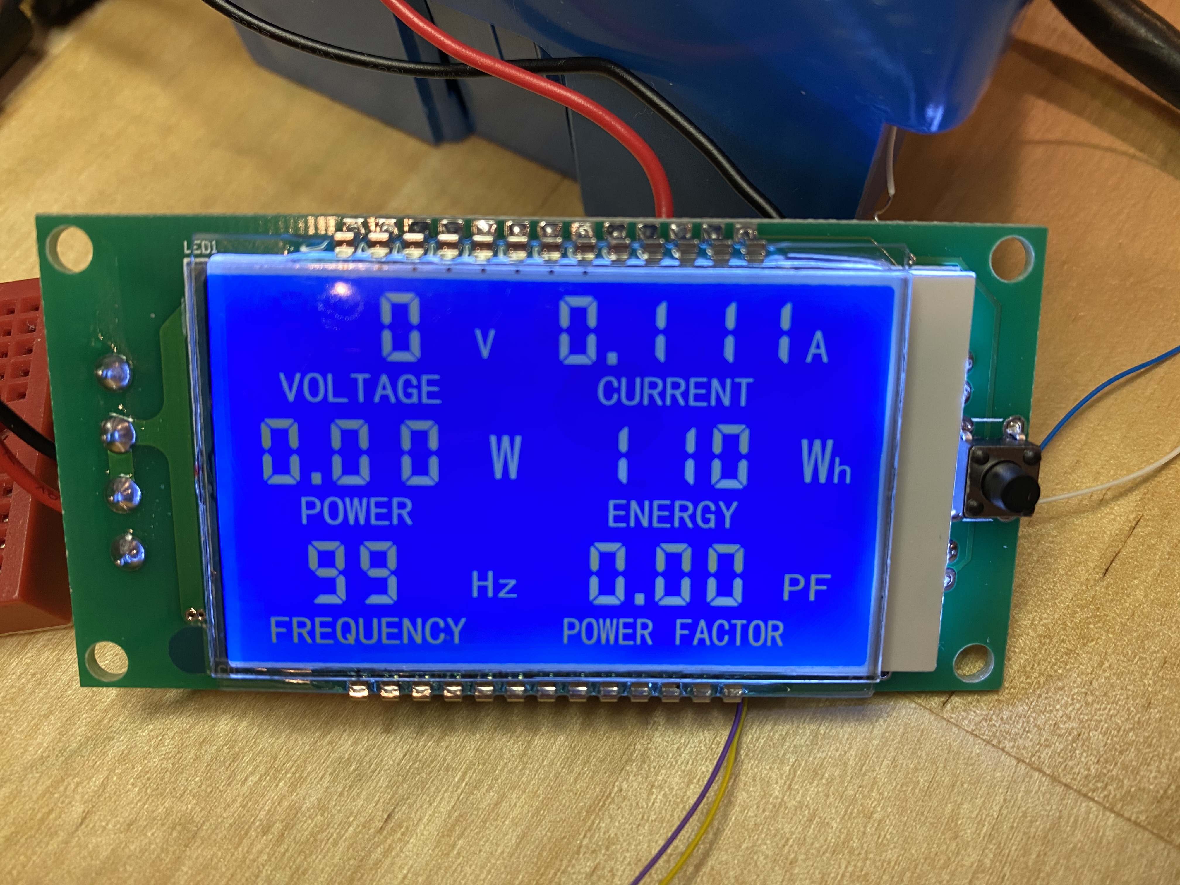
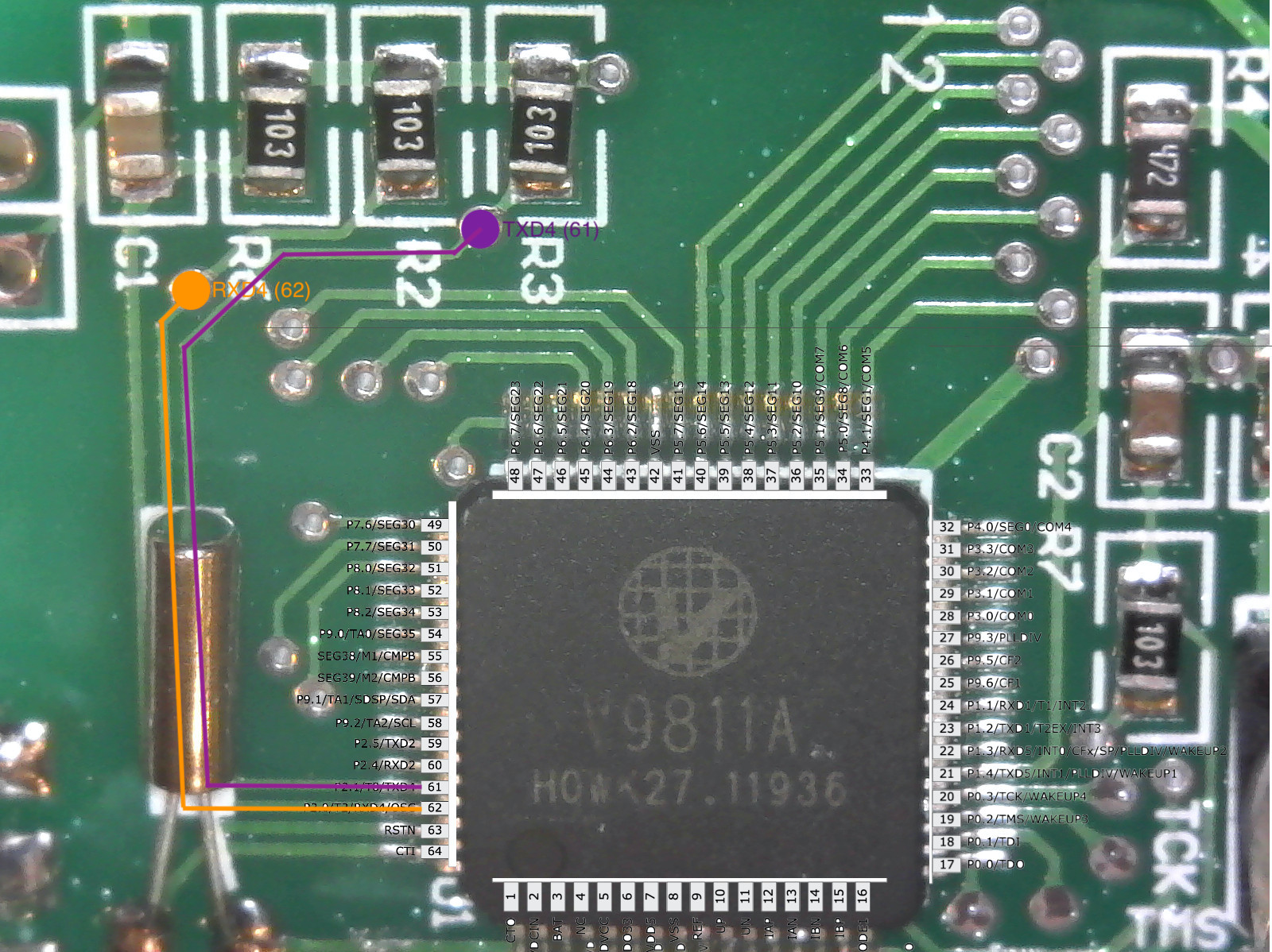
Here are some pictures of the set up. I promise you there’s no 120V exposed or connected to the controller. I hope I am not that stupid (and if I am, I hope I have some redeeming qualities)
I understand what you’re saying, but there’s a part of me that wants to believe the developer of the firmware must have used some serial output that is not connected for some reason.
Maybe i’m just being too optimistic.
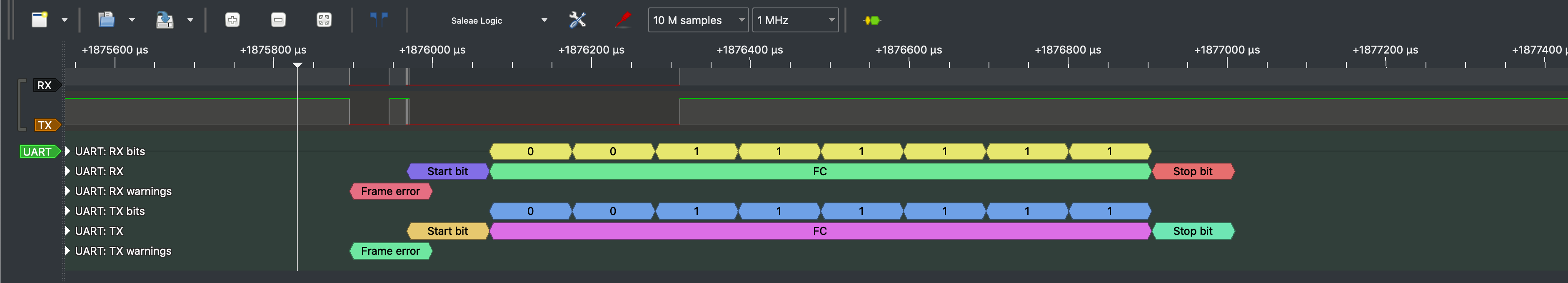
I’ve mapped the chip to the datasheet, and the only TX/RX pins that have connection are 61/62 (TX4/RX4) but i’m not really getting any information on those pins when I start the device as you can see in the logic analyzer capture.
Used it for what? Debug printfs maybe? What is it you’re hoping to find? It looks like they use JTAG for programming and potentially debugging.
Can you determine where they go? It looks like 61 and 62 are also available as GPIO pins so it’s a long-shot to think they’re being used as a uart, but if you can determine what they run to it might shed some light.
In the US split phase system, the neutral is earthed.
There shouldn’t be any current between the two unless, as Robert would say,
the neutral connection falls off upstream of the load.
Bummer…
At the risk of further advertising my ignorance, is it practical to try and see if the display signals can be used for this puporse? Or is it possible to see if using JTAG will provide something like that?
That’s true here too, but that connection only happens once at the fuse box. From there, the Active and Neutral that run to the power points are each small resistors. Depending on the loads and the lengths of the runs, Active will be a few volts lower than it is at the fuse box, and Neutral will be a few volts higher. Joining Neutral and Earth at one of the power points will trip the earth leakage breaker because you’ve provided an alternate path for the current.