Temperature yes. Flow meter probably - if the pulse is compatible @Robert.Wall may be able to help. Not sure if the EmonTX can power the pulse meter - it would certainly need a 5V supply rather than rely on the AC-AC supply.
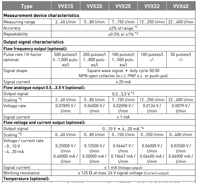
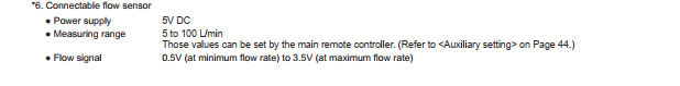
From the data that I’ve looked at, you should be able to use the “frequency” output of the flow meter, using the NPN Open Collector option. The power requirement at 15 mA means your emonTx and the flow meter need to be powered by a 5 V d.c. USB power supply.
You can connect two DS18B20 temperature sensors. Unless you use the screw terminals, you will probably need the RJ45 expander.
The emonTx pulse input uses the internal pull-up resistor, therefore your pulse output needs to pull the input down to register a pulse. The open-collector NPN transistor will do that.
(RL is inside the emonTx’s pulse input.)
If your German isn’t up to it, Electropedia is your friend.
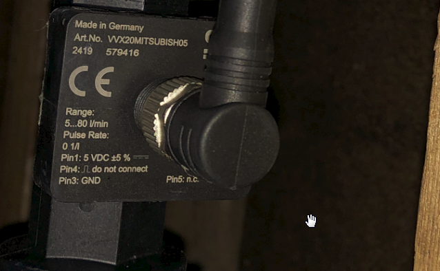
When I look at the flow meter manual it says to refer to the ‘type plate’ for the pin outs. On this it says ‘do not connect’ next to Pin 4, which is the pulse pin.
BTW I am planning to purchase a dedicated, second, emonTX for the heatpump. I will then be able to locate it next to the temperature sensors and flow meter.
I can’t read the part number on that - but it looks as if you have a version with an analogue voltage output, and you can’t use that with an emonTx, because it doesn’t have a spare analogue input brought out onto the PCB, let alone to a terminal you can connect to.
The best solution I can think of is to add a low-powered Arduino instead of an emonTx and use the analogue input of that to read the flow meter output, add the necessary bits for temperature monitoring and generate a serial data output and feed it directly to wherever (and I can’t guess where or what that is).
The only alternative is to heavily modify one of the inputs of your emonTx to remove pretty much all of the input circuitry.
As is often the case, we’re missing important information - whether this meter has been bought for the purpose (and if so, it looks as if the wrong one was purchased) or whether it’s part of an existing installation that we need to interface to (and not materially affect when the connection is made).
Which version of the flow meter? - the one with a 5 V d.c. supply (because that can be common to the flow meter and the emonTx/TH) and with the pull-down pulse output.
I don’t know pipe size, if temperature is required, etc, so I can’t be specific.
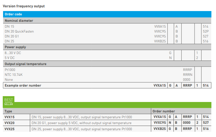
I think it’s VVX9CS N B 0000 2 XXX
I don’t know what the last 3 characters should be - 52P | 527 | 528 - that depends on the pipe fittings.
(The copper I usually deal with doesn’t have a hole down the middle )
Studying the data sheet more closely, it appears you get an analogue output as well. Which questions the label in the photo: Pin 4 (per the manual) is the pulse output and never anything else according to the diagrams, the label says 1 pulse per 1 litre (I think - but whatever, it does give a value) yet the label also says “do not connect” to pin 4.
I’d be inclined to put a multimeter on volts from Pin 4 (+ve) to Pin 3, a 5.6 kΩ resistor (or bigger) Pin 1 to Pin 4, and see if there are pulses there.
I was only thinking about if from the perspective of the 3 methods to read the flow - Pulse (frequency), Analogue, and Voltage&Current.
I think these different means are mutually exclusive; you can only have one of them at a time.
This tells me that is wrong, although you could get freq without analogue so the combinations are down to the part number.
Any analogue quantity is useless, as there are no available analogue inputs in either the emonTx or the emonTH - if there is one not used, it’s almost impossible to connect to it (unlike the emonTx V2). So that only leaves the pulse output.
Hence my suggestion (Post no.7) to not use an emonXX but a simple 5 V Arduino, all the I/O there is uncommitted and perfect for this application: an interrupt for pulses, A DI for temperature sensors, and a 5 V analogue input as an alternative for flow.
Thank you for all the replies. Was out at the pub last night, so only now able to respond.
The flow meter was installed as part of a Mitsubishi Ecodan installation. It connected to the Ecodan contral panel and provides a flow input for its own crude energy meter. It only shows, on a monthly basis, energy delivered and energy consumped. It does not show an instananeous COP.
The full part number is visible in the picture below. Meanwhile I will digest the dicussion…
What I want to do is turn off the Ecodan energy monitoring and use the existing flow meter for the Emoncms feed. This will avoid me having to try to add second flow meter into the system.
The part number implies a device produced specifically for Mitsubishi .
I’m inclined to agree. Looking at the Manual, the ‘frequency’ part 5.1.1 does not include ‘optional’ in the description, implying it is available on all devices.
Under section 5.1.5
The frequency output can be wired together with the optional functions. However, not every
combination is possible.
In principle, the pins 2, 4 and 5 can only be assigned with one function at a time. A multiple
assignment is not possible.
That I think is poor translation and means that only one of the pins 2, 4 or 5 can be used at any one time.
Thanks. I will have a closer look later and put a multimeter on it.
Interestingly I managed to find the bit in the Ecodan manual for the flow meter. It only references an analogue reading, not the pulse.
So, I am thinking that the pulse is part of the standard flow meter, but has been labelled as ‘do not connect’ as this is an OEM meter and the pulse would never be used within an Ecodan installation.