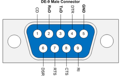
I took the moment to do some measurements on the TI-M12 module; Even with my multimeter set to 20MegaOhm I measure no contact between the RS485 pins and the housing ground and/or power supply pins.
Housing (grounded) to both power pins: No connection in one direction, 4 Mega Ohm if I reverse the measurement pins.
Same between RS485 pins and housing ground.
With the meter set at 20 Mega Ohm it does not detect connection between the RS485 pins and +24V DC and 0V DC.
About 350kOhm between RS485 + and -
So I guess it is a fairly well isolated gateway then?
Is there anything else I could test for?
Having written the above and with my thoughts going over the day I remembered that the quality of the connection of the RS485/Modbus wires in the DB9 connector to the TI-M12 was not optimal. Some fibres were broken/sticking out. I do not remember seeing any of the fibres touch either connector housing ground or eachother but I can’t rule it out either.
At the moment I reconnected signal ground to the DB9 connector at the TI-M12 side. I measured no contact between the RS485 contacts and signal ground, as well as the RS485 contacts (including signal ground) and housing ground with the multimeter at 20 Mega Ohm.
I am going to test again for a few weeks but still: if there is any good reason to measure anything else I would be happy to know.
Maybe, maybe not. Some manufacturers regard capacitor isolation as galvanic isolation. So measure it with a DC multi-meter and it will look like it is isolated. Unfortunately capacitors have exactly the opposite characteristics required from an EMC point of view, offering low impedance to higher frequencies. You really want transformer coupling or opto-isolation for true galvanic isolation. Only way to know what you really have is ask the manufacturer or open it up.
I am surprised your Waveshare seems to have blown up, I haven’t used that particular device, but many other Waveshare RS485 transceivers, never had any failures (Unfortunately that doesn’t really help you, sorry).
Much as I hate trusting what AI says, here is what the Google LLM AI concludes …
The conclusion that the TRENDnet TI-M12 lacks galvanic isolation is based on official manufacturer specifications rather than third-party forum summaries. The official technical documentation specifies ESD and surge protection limits without listing an isolation voltage rating or certifications required for a galvanic barrier. For further technical details, visit TRENDnet. [1, 2, 3]
I see that they recommend using a TI-S100 for making RS422/485 connections (DB9 to screw terminal). Would have made terminating the twisted pair easier and also easy to add an RS485 120R terminating resistor. I know from experience it is very fiddly to solder DB9/25s, and all too easy to short pins.
The thought I had was, what test voltage @Martijn_Hinderdael does your multimeter apply to measure those resistances? Will you see the same at a higher voltage - closer to the 24 V working voltage or even close to the insulation test voltage they claim?
I haven’t soldered a DB9 or DB25 for a long time, but provided your wire is not too fat, I’ve not had a problem with whiskers.
Hopefully a silly question: you did count the pins from the correct end?
Fun to see that a different connector was supplied to me with the TI-M12 then…
I think I will go for an industrial grade connector+housing with such a layout that I don’t have to bend the wires 90 deg at the screw terminals.
Waveshare has already responded to my burnout event, asked for pictures and I asked Trendnet about how they isolated between RS485 and the rest of the unit.
Tot test my multimeter I need another one…hopefully I find one close to my home this afternoon.
I was quite surprised as well to see that Waveshare unit burn up. Even a company generally using Schneider PLC’s for industrial application suggested me to use a Waveshare RTU to TCP gateway for something else in my home and informed me that their stuff basically works well all the time. @Robert.Wall I did not connect the power supply to the RS485 contacts if that is what you are inquiring about. Polarity of 24V DC was correct. I don’t see any RS485 wire mixup either.
No, I did not mean that. My question was: depending on the range, many multimeters test resistance at a voltage low enough to not cause a P-N junction to conduct. Is the isolation still good at a voltage significantly above this? It might well be on the MΩ ranges, it is worth looking.
Just tested my multimeter with the neighbours: His multimeter was a Fluke meter (did not memorize the Type but given Fluke I presume it is high quality)
200 Ohm → 2.5V
2k → 0.254V
20k -->0.254V
200k → 0.251V
2000K → 0.233V
20M → 0.133V but my multimeter started to show 11M Ohm instead of no connection
2000M → 1.507V and my multimeter showed 21 M Ohm instead of no connection.
I will re-check if I had the correct pins later today.
I double checked if the contacts on the female connector correspond to numbers 3-4-5 on the male one using a multimeter to see if the screw terminals were connected to the correct pins and they are.
I decided to re-do the measurements all with the multimeter set to 2000K.
Pin 3 to housing earth: NC
Pin 4 to housing earth: NC
Ping 5 to housing earth: Some 200k and steadily climbing to over 600k (I stopped there) with red multimeter pin on pin 5 and black on housing earth. Some 15k and steadily climbing to well over a few hundred k and then I decided to stop measuring.
Pin 3&4 to 0V and +24VDC: No connection in both directions
Signal ground to 0V and +24VDC: Starts at 180kOhm, quickly drops and then no connection.
“In both directions” means that I reversed the terminals of my multimeter and repeated a measurement.
The voltage is what the Fluke measured when your meter was measuring resistance on the various ranges?
I think this is telling me that on all except the 2000 MΩ range, the test voltage was 0.25 V, and about 1.5 V on the 2000 MΩ range. What you are reading is the resistance by which his Fluke loads a voltage source ( = your meter) – which only comes within range on the highest two ranges.
That means you were charging a capacitor with the battery inside your meter, the “resistance” ( = a constant ÷ current) rising as the current fell as the capacitor charged. So there is a capacitor between its GND (5) and earth.
I’m not sure what I interpret there. “Drops” – do you mean the resistance moved towards 0 Ω? This could have been discharging the capacitor you charged via pin 5, then maybe charging it to the opposite polarity.
If there is a voltage difference carrying spikes and interference generally between the earths at each end of the RS485 link, then that capacitor could be creating a current path via your GND pin (5), so putting the interference on your GND voltage.
After your comment I decided to re-do this exercise in an expanded way and take a video of the whole thing so I could recapitulate exactly what I saw and the results were kind of funny:
I measured resistance between pin 5 and housing ground with the multimeter set at different Ohm ranges:
200 Ohm: 0.L (this is what my Voltcraft 4095 meter shows with no connection
2k: 0.L
20k: 0.L
200k: 0.L
2000k: 0.L
20M: 0.L
2000M: Changing values between 12 and 20 MegaOhm.
20M: 0.L
2000K: Suddenly ~ -500K and increasing towards zero and then increasing above zero. I did not wait until we reached some kind of maximum.
It was kind of hard to keep my multimeter pins exactly on a pin and the other one exactly in place as well.
After that it stayed like that. So every time I touched pin 5 and housing ground the resistance value moved in one direction. I tried once up to a displayed value of some 1500kOhm or so.
Then connected the multimeter with the dial set to measuring capacitance: It can go from 2 nanofarad up to 200 microfarad. Everything shows 0 stably irrespective of whether I switched the multimeter cables to see if it would respond different with polarity the other way around.
So apparently it has some kind of condensor that was not activated with the meter set at 200 Ohm (which produced ~2.5V as testing voltage with my neighbours Fluke meter) but did get activated at 2000M Ohm which produced a testing voltage of ~1.5V.
I doublechecked both testing voltages with the Fluke meter by the way.
I think it probably was ‘activated’, you did not see it because your meter fed a relatively high current and everything happened too quickly.
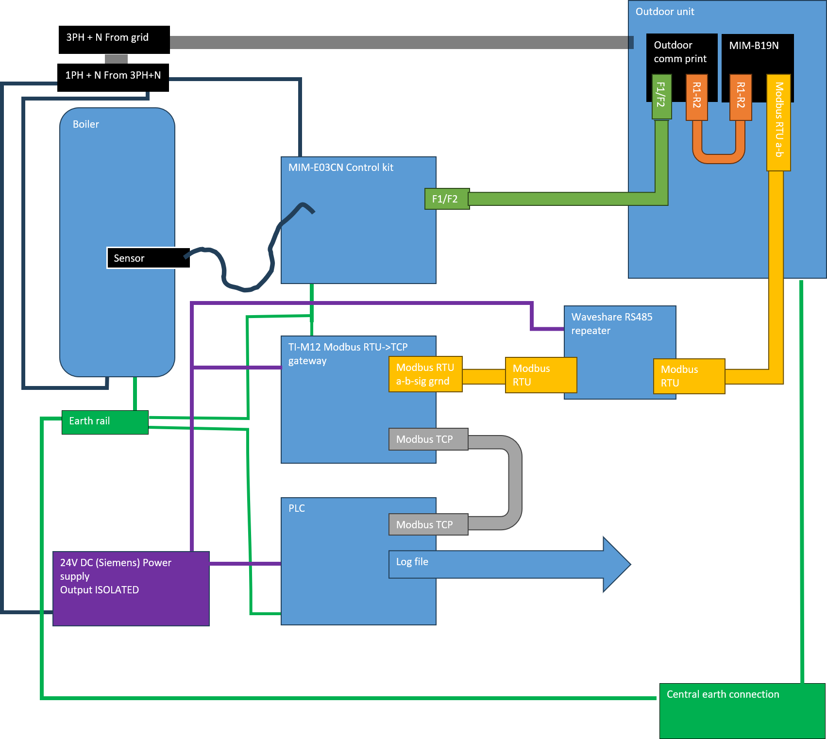
Going back, the data connections are in the image on post no.29, but you have now changed the details by adding the RS485 repeater. Could you provide a drawing as it now is – or will be with a good data isolator, and add the power supplies, whether they are isolated or not, the zero volts connections, cable screens and all the earth connections and show whether these are connected to a common earth point (and whether buried metal or provided by your electricity supplier).
I have my own buried earth connection (some pin rammed into the ground at ~20m cable length from the sketched setup.
As the waveshare repeater got burned up it is currently not present but this is what it would have been had it stayed in good condition.
Is this sufficient or is there anything else I should illustrate?
To help me investigate further, could you help me by answering the following questions?
Is the RS-485 interface of the TI-M12 galvanically isolated from the DC power input, Ethernet interface and chassis/earth?
How is RS-485 pin 5 (signal ground) internally connected?
Is it connected to DC negative, Ethernet ground, chassis ground, or is it floating/isolated? Should I connect the cable shield+drain wire to signal ground if the other end only has A and B connection?
If galvanic isolation is present, what is the specified isolation rating (Vrms or VDC) between the RS-485 interface and the rest of the device?
Response from Trendnet:
Thank you for your patience. Plea se find the requested information below.
The RS-485 interface of the TI-M12 is not galvanically isolated from the DC power input; however, it is galvanically isolated from the Ethernet interface and the chassis/earth ground.
2, RS-485 Pin 5 (Signal Ground) is internally connected to the system ground—which is tied to the DC negative terminal—via a 33 ohm resistor. It is not floating or isolated
No, RS-485 Pin 5 (Signal Ground) is connected to Signal Ground.
The RS-485 interface of the TI-M12 is not galvanically isolated.
Now with my DC power supply being galvanically isolated from the 230V net I would think that essentially my RS485 should be totally galvanically isolated.
From the 230V net via the DC power supply
From ethernet and chassis ground via the Trendnet.
Yes, but the galvanic isolation is in the wrong place. With Ethernet you normally get galvanic isolation at the point of connection with miniature coupling transformers, so I guess that is what they are describing, everything else inside the unit is electrically connected together. So while your power supply is internally galvanically isolated interference can get in through the wiring or the PLC. Ideally the galvanic isolation should be at the RS485 transceiver so interference injection can easily be controlled. This is the idea of the isolating repeater, you haven’t got an ideal device in the T1, so you approximate the ideal.
When in the dim, distant past I used to design hardware for distributed industrial control systems, the gold standard for EMC was 3 port isolation. The power input is galvanically isolated, the inputs are galvanically isolated and the outputs are all galvanically isolated from the internal electronics. You have imperfect single port isolation, on a compact system it would probably be OK.
So personally I would still try the isolating repeater, that would at least confirm the theory (guess?) it is conducted interference.
I am off on holiday so will be off-line for a few weeks, so good luck with your further investigations.
Everyone, I have had another few weird communication errors and decided to call it a day for the heating season with the MIM-B19N and switched back to my Intesis gateway for the time being.
Upon opening the DB9 connector to the Trendnet gateway while making the switch back one of the wires again had whiskers even though I am confident that I put all wires in with surgical precision. So maybe in the end it may turn out that most if not all of my problems boil down to this DB9 connector bugging me…I don’t know.
But at the moment I lack the time and energy to give it another try (or few tries if I’m not lucky) with a better connector.
Knowing how the months ahead of me are looking I need the peace of mind I had with the Intesis that basically worked flawless more than the additional flexibility and higher energy efficiency I get out of the Samsung MIM-B19N.
Honestly a lot of thanks for the support everyone, I may pick up this topic again later on if I give the MIM-B19N another go next spring.