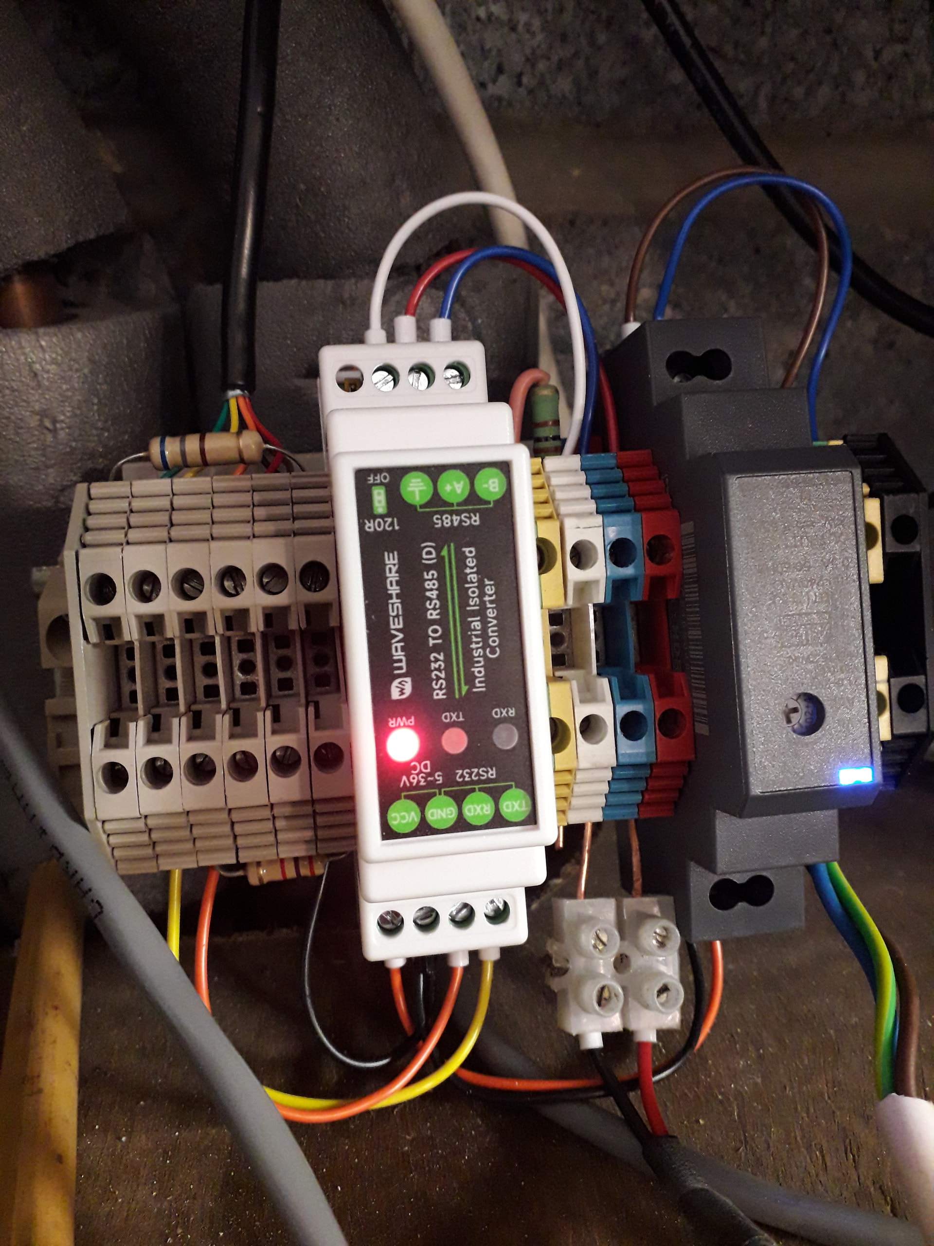
I currently have a Samsung AE080RXYDGG/EU heat pump that is showing 101 error codes every few weeks or so. I have not been able to connect it to a certain event in my house or in the heat pump itself so far.
It did not show these with a Intesis INMBSSAMO4000 modbus interface but it does show them with a SAMSUNG MIM-B19N Modbus interface.
As the Samsung Modbus interface is capable of setting the outlet temperature up to 65C and the Intesis interface is limited to 55 I would really like to stick to the Samsung one.
What did I find and improve so far:
-Changed the solid core STP cables to stranded STP, both the F1/F2 cable between control kit and outdoor unit as well as the modbus cable.
-F1/F2 cable shield was and is only grounded at the outdoor unit. Wire cross section 0.75mm2 according to Samsung manual (this cable was quite a search to find). 20m, only within 50mm of the power cable for 1m or so.
-R1/R2 is a few cm of 2 separate wires between outdoor unit print and the MIM-B19N which sits perfectly locked in a dedicated slot in the plastic frame that the outdoor unit has.
-Modbus cable also changed to stranded STP now.
What did I diagnose so far: Values below measured in control kit 2 days ago. I did most of the checks below also a few weeks ago on the outdoor unit with very similar results.
-Ground-N resistance ~50 Ohm after long dry weather, ~20 Ohm after some rain
-Ground-N voltage <0.5VAC when resistance N-PE is ~50Ohm, 0.02V DC/0.3V AC when it had been raining
-Phase voltages ~231-232 V with less than 2V between them even if 1 phase is for instance supplying a 2kW heater (laundry machine, boiler, …)
-F1/F2 shows ~0.28V DC when everything is fine. Just over 1.1V DC when the error code is active.
-Disconnecting the control kit from power keeps the voltage on F1/F2 at >1.1V DC.
-Disconnecting the outdoor unit reduces the F1/F2 voltage to about 0.1V DC
-Putting power on the outdoor unit back on brings it back to 0.286V DC and communication is fine again.
-F1/F2 voltage stays at ~0.286V DC for days/weeks and when the error is there it is suddenly > 1.1V
-No hard statement but the error seems to be less frequent since I put a delay in the start of an electrical boiler so that it would give the heat pump a minute or 5 to start rotating the compressor before deciding it was not going to start and the backup heater was necessary.
-Cable routing was deemed acceptable by the person Samsung Netherlands directing me to for maintenance of my heat pump. He was going to contact Samsung on my issue but I have no feedback so far after a few weeks.
I am getting to a point where I would want to check my signals with an oscilloscope (which I don’t have access to) but I have trouble finding someone who services heat pumps in my vicinity who is in the posession of an oscilloscope.
Pending me either finding or purchasing that scope I want to troubleshoot as much other things as possible.
One striking difference is that the Intesis gateway had a galvanic separation between R1/R2 and Modbus and it is not clear if the MIM-B19N has that as well. Now I guess that it should basically work…I mean Samsung Modbus gateway on a Samsung heat pump with an exactly correct place in the heat pump to click it into…One of the theories I got from AI that possibly the print containing the communication contacts in the outdoor unit is malfunctioning but that can -as far as I know- be confirmed best with an oscilloscope.
Questions here;
-Any hints or links to best grounding practices for this model Samsung heat pump and modbus + F1/F2 cable shields?
-Anything else I can troubleshoot / diagnose/ measure without buying the oscilloscope?
No! I have not read any recommendations to do so either so far…but I am willing to try if it there is sensible logic behind it.
Any explanation on how that would influence the re-occurrence of the DC voltage increase over the F1/F2 contacts?
What is on the end of the Modbus cable remote from the B19? If it is a cheap USB->RS485 convertor, then these are not galvanically isolated so may be the cause of your strange behaviour. In my experience with Modbus/RS485 on real industrial plant, for lengths below 10m, the cable quality is not very important, it would work OK over a bit of wet string (provided it was twisted pair wet string).
Although that looks like a professional bit of kit, it doesn’t specifically say the RS485 is galvanically isolated. So (lot of assumptions here) …
Since the Intesis does not exhibit the problem and is galvanically isolated, but I don’t believe the B19 is and does exhibit the problem, it is likely galvanic isolation is significant.
The only way to clear the 1.1v on F1/F2 is a power cycle suggests a non-destructive interface chip latch-up, probably caused by a large noise spike, probably caused by un- suppressed switching of an inductive load.
If that theory is correct, then @Johnmo suggestion is one way of slowing down that spike. I guess I would be inclined to open up the Trendnet first to confirm if the RS485 is galvanically isolated , it should be obvious from the layout, a large track free gap somewhere in area of the RS485 interface chip. If it is, then it is looking like a noise spike coupled into the cable.
Another possible mitigation is a split termination on the Modbus line. Instead of trying to stop the spike getting in, you provide it with a better route back to ground rather than through the Samsung electronics.
The normal RS485 termination is a 120R resistor across A and B at both ends of the bus. You split the 120R resistor into 2 x 60R resistors in series, then connect the 60R common point to ground, either directly or through a 100R resistor. That way any noise spike induced into the cable sees a low impedance path to ground and if you are really lucky it is much lower than the path through the Samsung electronics. Couple of caveats
This may increase the load on the RS485 Tx drivers, so should be used with caution on a bus with many devices connected, but just for 2 devices it should be OK.
No guarantee it will work. I have seen apparently strange things during EMC testing. For instance, a PCB bolted to a steel plate earthed at one point. When spikes were injected into the far side of the steel plate the electronics keeled over. Seems the spike energy preferred to travel through the PCB than the steel plate. But of course, it had a fast rising edge, so the surface area of all the tracks on the PCB presented a much larger conductive surface and therefore lower impedance, so a significant noise current passed through the PCB.
The TI-M12 is connected to a 24V DC Siemens power supply that I ordered with my Siemens LOGO PLC.
Only thing directly connected to the outside world on that thing is the casing connection to ground…
The modbus RTU cable is terminated with a 120 Ohm resistance on the heat pump side but not on the TI-M12 side (I could not fit a proper resistor in the DB9 connector).
Do you still consider it plausible that some spike could travel to the Modbus cable from the TI-M12 side with this setup?
If this was a 1-phase TNCS installation, then probably not. However, the AE080RXYDGG/EU appears to be 3-phase, and the 50R resistance between Earth and Neutral suggests a TT installation, so my probably not becomes possibly yes. In fact your connection of the enclosure of the T1-M12 to Earth with this setup may well be the injection path of the noise spike. If you don’t want to open the T1-M12 up to have a look, since it has RS232, then you could buy something like …
to prove/disprove the point (it’s a lot cheaper than a 'scope). I use this device in my system.
I have a TT installation (3Ph + N from grid and my own Grounding Pin).
Today the error recurred again and luck has it that I just modified my PLC program this weekend to start logging some things every 2 seconds.
See the file below.
Long story short: I see no large electric load that switched on or off at the moment of the ERROR 101 first being logged or in the few minutes before.
That said I do notice a peculiarity in the column that calculated my home’s consumption. Presume that that calculation is false. Update: The calculation is correct. I think that either the logger of the solar inverter or the logger of the smart electricity meter is not updating every second. I do request values every second but that does not mean that the reported values are updated every second.
Maybe something not being the heat pump was switched on at that moment but I don’t see anything big.
@toadhall I would like to be able to measure electric separation by for instance measuring resistance between pin X and Power supply pin Y or so.
If that is not possible I could consider opening up the TI-M12.
I have asked (today) for numbers on the insulation at the manufacturer by the way.
For just a few seconds I thought of grounding the casing to the modbus cable shield to see if that would avoid this spike transfer, but the whole casing including mount is metal and mounted on a metal and grounded DIN rail.
The Intesis casing was plastic, possibly for a purpose with today’s knowledge…
Would it make sense to connect the cable shield of the Modbus cable to the outdoor unit instead of the signal ground pin at the TI-M12?
I have been using (next to this forum) a lot of AI on this and one thing that keeps coming back is the suggestion to disconnect the shield at the TI-M12 side.
Feels kind of counter intuitive for a mechanical engineer to first buy a cable with shield and then decide to not connect it…but it is worth a try. @toadhall would you consider it a plausible experiment to disconnect signal ground and with that also the shield of the Modbus cable at the TI-M12 side?
From then only Modbus A and B would be connected between the TI-M12 and the MIM-B19N
Yes, often shielding causes more trouble than it is worth. Instead of interference being induced into a short length of bus it is propagated over the entire length of the cable. It will appear as common mode on the twisted pair, so the differential receiver won’t see it, but it could cause latch-ups in the interface chip if the induced interference is high enough. I would be inclined not to leave it floating in the long term (it may accumulate static or resonate), but worth it for a short test.
RS485 is really a 3 conductor bus, A, B and GND (better named reference terminal to avoid confusion with true Earth). But as most modern transceiver chips contain bias resistors it doesn’t need the ground, in fact the B19 only has A and B.
I must say that with all these kinds of discoveries I am making on just simply connecting a heat pump to a modbus network; my respect for the engineers developing computer hardware where basically anything works plug and play when it comes to communication lines grows by the day
Update: I disconnected the shield of the modbus cable last thursday. Today I had the 101 error again.
Possibly the shield is not such a big factor in itself?
I think I missed this, are you saying you had the third RS485 signal, the GND connection, connected to the shield of the cable? If so that would likely be a very bad thing. So yes, I would connect the shield to the grounded metalwork of the outdoor unit, especially if the F1/F2 cable and modbus cable travel together over a significant part of the 20m. When connecting the shield grounds to the chassis make the connection as short as possible otherwise you will suffer from the pig-tail effect, from a high frequency point of view the shield will not be connected to ground at all.
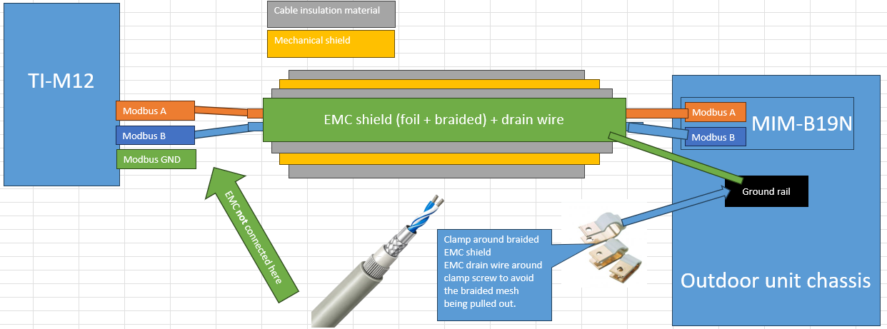
This is the cable I purchased for the Modbus connection.
Although the picture does not show it, the cable has a drain wire which is connected electrically with the shield.
The mechanical shield is not connected…if I remember well.
Mechanical shield is certainly not connected to the outdoor unit Chassis but I am not 100% confident if it is also not connected to the EMC shield.
Yes, the outer wires are just for mechanical protection (like mains Steel Wired Armoured cable). So the ideal connection would be a clamp similar to the one I pointed to clamped around the braid shielding and the drain wire just used as a mechanical restraint to stop the cable being pulled out of the clamp. Proper RS485 cable would have 3 cores for A, B and GND. I did come across a suitable Belden cable years ago but haven’t seen it in living memory. Now they just suggest you use twin twisted pair, one pair used for A and B, the other pair used for the GND.
Nice new recommendation after all my searching and asking for the best possible cable for the application
But given the cable that I have what would be your recommendation on how to connect it?
The cable has a drain wire (if that is how I may name it) connected to the EMC shield and a mechanical shield basically isolated from the EMC shield.
On the Modbus RTU to TCP gateway side I have connections for A, B and signal ground and if I buy a new DB9 connector I can create a possiblity to connect something like the mechanical shield to earth.
On the outdoor unit side I only have Modbus A and B connections and the possibility to connect something to the earthed outdoor unit chassis. That something could be EMC shield, mechanical shield, both or none of the two.
Given that it is not known what is inside the T1-M12, I would only connect A and B at that end. Connect the braids on both F1/F2 and Modbus cable to chassis ground at the outdoor unit using a good high frequency method as described earlier. That clamp should be tight enough to make good electrical contact but not so tight as to crush the cable, hence the need for mechanical restraint. In your situation you can use the drain wire, but normally the cable would go through a gland in the equipment casing that would provide mechanical restraint. I would also connect a few strands of the mechanical shield to the same screw you connect the drain wire, this will give extra mechanical restraint and also avoid having the mechanical shield floating. It won’t do anything for the EM immunity since the braid and foil shield cannot really be improved on.
Shielded cable is good in high RF environments (so radiated interference), but useless for conducted interference, which is what I think you are suffering from (unless you live next door to Schiphol, Huizen or Hilversum)