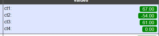
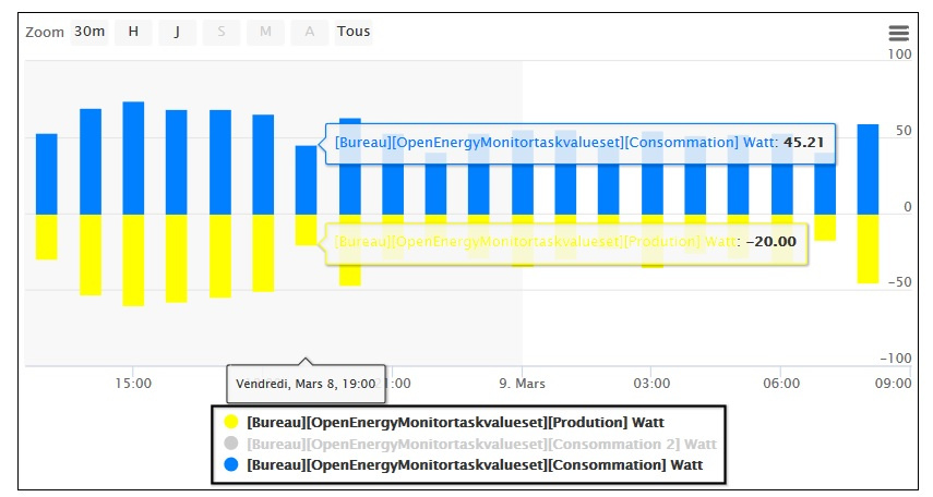
I have my functional shield emontx. I wanted to do a test: connect 3 sct on the same circuit. 2 on the positive direction and one on the negative direction (to simulate energy production).
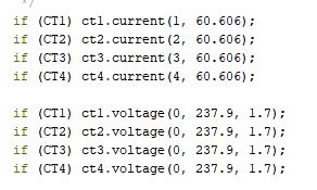
As you see on the pictures I have no value that is the same! the biggest difference is the difference between a positive and a negative value! What can explain these large differences in results? In the arduino sketch the formulas are the same …
Thank you!
Please don’t link to files on external sites. Unlike others, we want you to attach your screenshots, log files, etc to your post. If the external site goes away, the material is likely to be lost forever. If that happens, when someone reads your post, your question and our answer will have little or no value.
But you are measuring only 50 W! the maximum you can measure is 25 kW, so you are below the range where the measurement is accurate. Even if you have calibrated your Arduino accurately, the current transformers are only guaranteed to be accurate to within ±3% above 10 A (≈ 2300 W). Below about 200 W, electrical noise in the measuring circuits will add to the current you measure, and it is likely to be that, which is causing the positive values to be larger than the negative
If you measure a much bigger load, I think you will find that the positive and negative values will come much closer, as a percentage.
The calibration instructions are in the ‘Learn’ section. Calibration will correct the errors caused by tolerances in the manufacturing of all the different components.
sorry for hosting the pictures, it’s an old habit …
Ok I understand that the caliber of 100A for the sct is not suitable for small values … we agree that the sct 100A is the only compatible with emontx shield? thanks again for the answers!
Not at all - but there is a limited choice of c.t’s that have a power rating that is high enough to provide the 1.6 V rms (approximately) that the Shield needs for the best resolution.
You have three choices:
1- If you do not change the burden resistors (the 33 Ω), then a c.t. with secondary current of 50 mA (at the maximum current that you want to measure), that is capable of generating 1.6 V at 50 mA is suitable.
2- If you change the burden resistor, then you can use a higher value of resistor to get a higher voltage. But the penalty for doing this is the errors in the c.t. get larger.
3- You can multiply the sensitivity of your c.t. by passing the wire through it several times. This will only be possible for low currents when you can use thin wire. For example, I test the SCT-013-000 using 0 - 5 A and a coil of 20 turns, and it reads 0 - 100 A. This is the best solution, if it is practical.
thank you for your clarification and your advice, it’s very nice!
In fact for now these are just tests on a power outlet of my PC … I wanted to be sure that everything worked properly. At term there will be the total consumption of the house and the production of my solar panels (~ 500W).