So I am new to EmonPi, but I know Linux and have existing Pi’s running around the house PiHole etc.
I also know networking, but know very little about power/energy monitoring. I have had Solar Panels fitted this week and want to monitor how much power is going back to the grid, as well as home much power I use, and lastly how much power my Solar produces. My setup is Type 2.
So my view is I want EmonPi with a CT clip for the cable in the meter box, and another CT clip for the solar feed. Now I have lots fo questions so I will list them below.
The AC-AC needs to be plugged in, as does the Pi USB power. I don’t have a double socket in range. So I plan to run an extension lead, but have read this which says “Extension leads are never a good idea for a permanent installation, so I’d recommend getting a double socket installed at some stage.”. Why is that, if I run a plug to some flex and the wire into a backbox with double faceplate, that is no different to a spur on my ring main. Only difference is a don’t need a part P because I have a plug on the other end. Can I do this for now? What is wrong with extension and AC-AC?
Assuming extension is a bad idea then I could locate the Pi elsewhere but would need really long runs for the CT clips, I am happy cutting the provided cables and soldering in some CAT6 to make longer, but what is the maximum length I can go?
Where my Consumer Unit and Meter are, I have a meter for my generation tariff on solar. But it is hard to access a cable to CT clip to for the solar, could I use a pulse sensor for the solar generation instead of a CT clip?
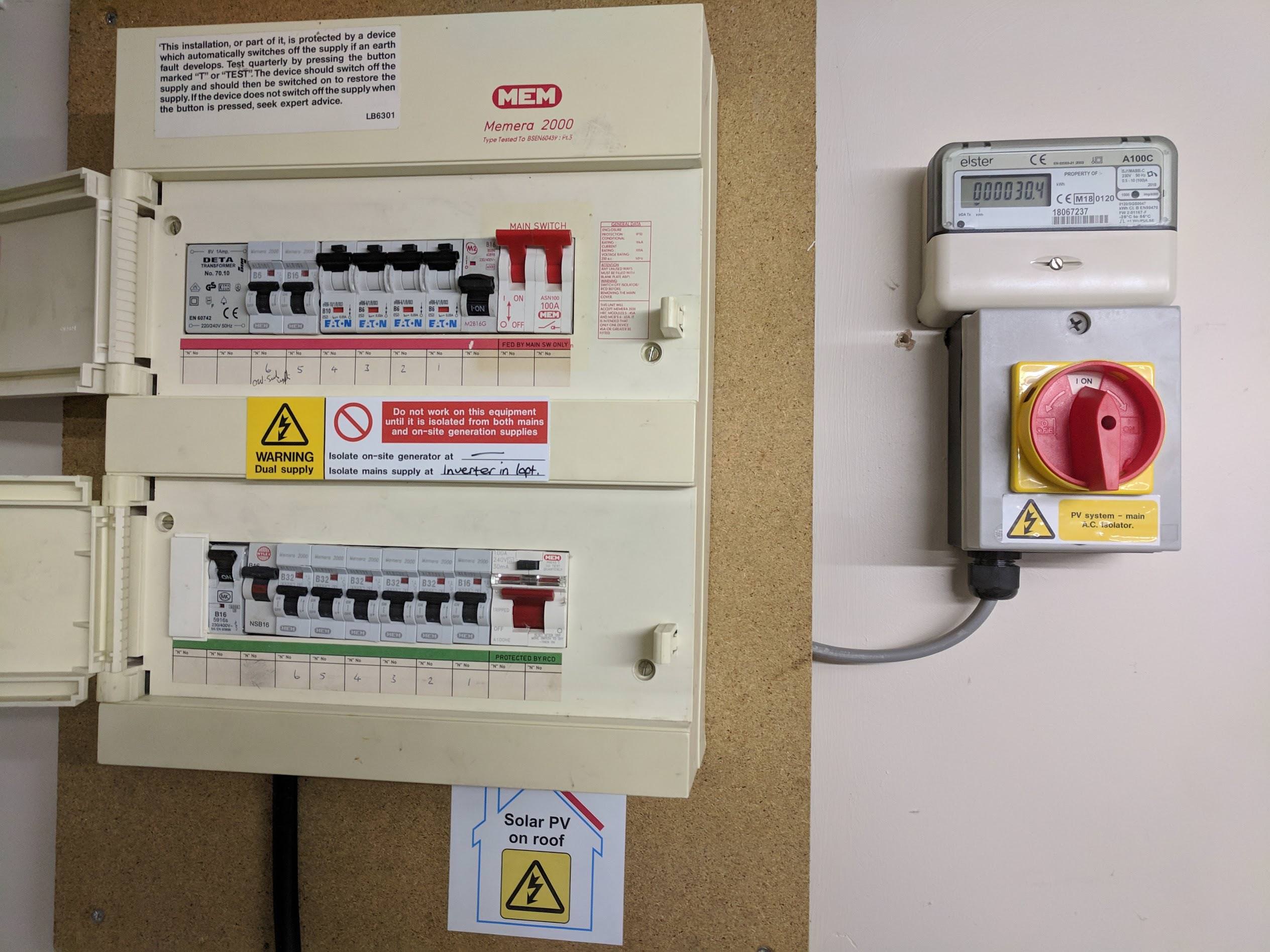
I have attaches pictures of my setup to help any advice. I am considering putting something (maybe the EmonPi maybe something else) in the loft next to the Inverter as easier to CT clip for the solar. Could I do the meter end remote in some way?
I have done a lot of reading on the site but I am still not clear on the difference between EmonPi, emonTx V3 & IoTaWattTM. If there is a simple comparison article somebody please point me to it.
tl;dr I want to extend all the sensors, is that possible? Can I extent the AC-AC adapter???
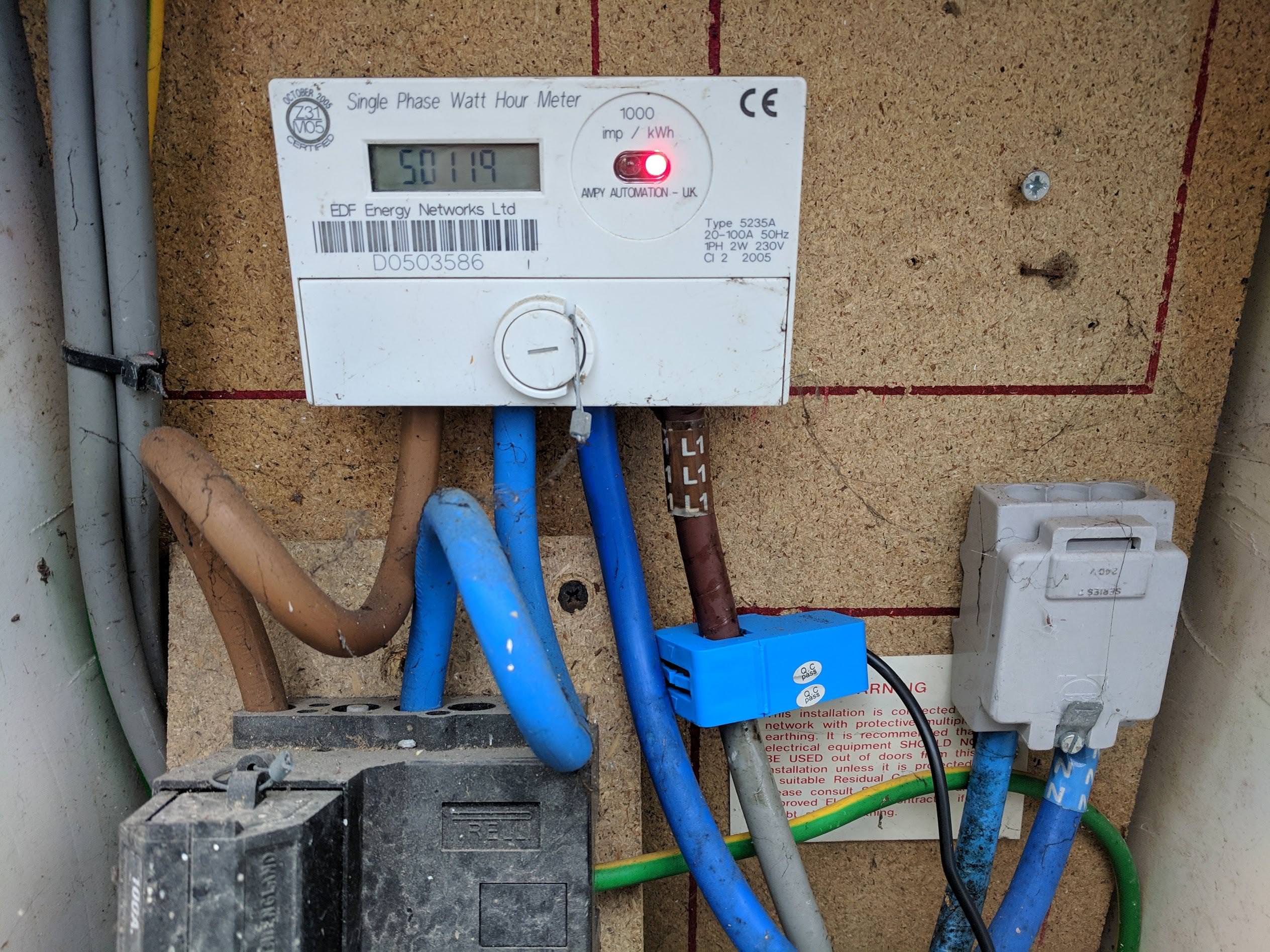
Show electric meter and existing CT clip used for the Powerdiverter which connects to the emersion for hot water. This powerdiverer has a remote CT clip running over RF, can I connect to this using EmonPi?
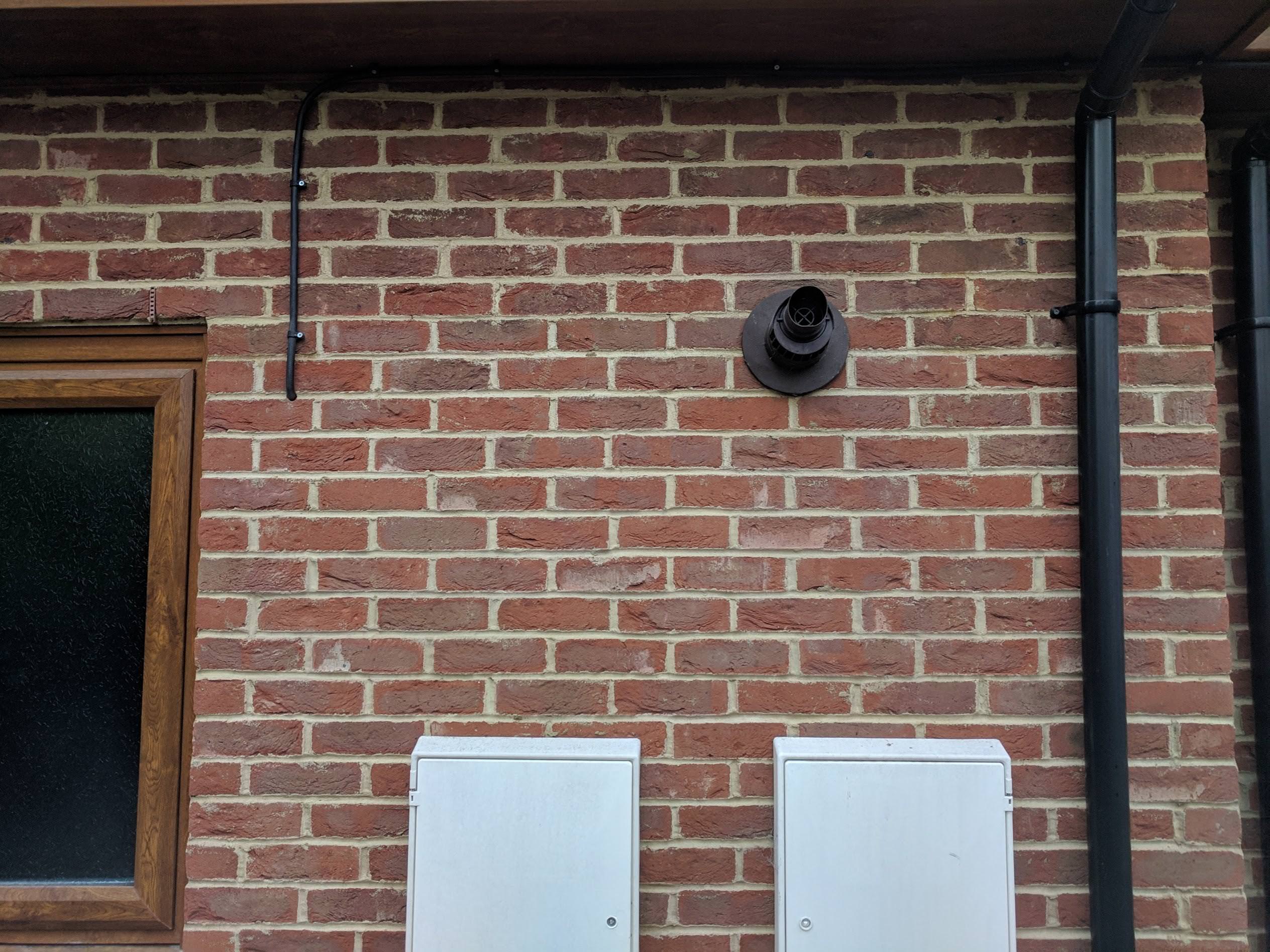
In the second to last image that black cable is the one from the inverter in the loft to the consumer unit, via the generation meter show in the last picture. That is why I think it will be hard to get a CT clip on it. Can CT clips be placed outside?
Edit - Moved pictures from 3rd party site to OEM. Moderator, BT
I suspect you’ve already found the ‘Learn’ section, there’s a lot of the basic theory in there.
An emonTx would do that, either with a c.t. or the optical pulse sensor, or an emonTH would do the pulse sensor only. But is there room in your consumer unit for a c.t? - from the picture I’m guessing that the P.V. infeed is to one of the 16 A MCBs.
The emonTx is a 1-voltage, 4-current energy monitor that transmits the readings by radio (or sometimes, a wired serial connection).
The emonPi is a 1-voltage, 2-current energy monitor that transmits the readings to a Raspberry Pi, all in one case. Also in there is a radio to receive data from one or more emonTx’s.
Worth a mention is the emonBase, which is an unboxed Raspberry Pi and receiver.
I have no personal knowledge of the iotawatt, and despite it being stocked in the shop, there is a limited number of experts here who can support it. The knowledge base for it is at https://community.iotawatt.com, where its creator has set up a dedicated forum.
Yes. There’s an article in the ‘Learn’ section with details for the c.t. You can do exactly the same for the v.t.
The key consideration is reliability. If you’re happy that it won’t get “borrowed” (and it sounds as if your “extension lead” is all but permanent), then that’s fine.
Not only hard, but it won’t read anything - that is a 2-core or 3-core cable! A c.t. can only go on a single-core cable, if the same current returns in a second core and the c.t. encloses both, the nett magnetic field (which the c.t works on) is zero.
Provided it is damp-free (you don’t want the mating faces of the ferrite core to go rusty), then it should be OK - but if I’m right about the type of cable, it won’t help you.
Thanks Robert for the reply. Really useful information!
I am now a lot clearer on the difference between EmonPi, emonTx V3 & IoTaWattTM. It sounds like I might need an emonPi and an emonTx (or emonTh with an optical sensor).
I am happier now I know I can use an extension for the AC-AC. You are correct it won’t get “borrowed” and wil be a permanent fixture.
Main Follow Up Question
It is interesting what you say about that cable from the Solar PV being a 2 core or 3 core cable. Where would I then clip a CT clip? or can I just go with optical sensor on the meter which is very easy to reach. Would there be a single core cable somewhere behind the consumer unit, and if so I guess I need an electrician to help fit the CT clip?
The cable will split inside the consumer unit. The line will go to the MCB, neutral to the neutral busbar and earth to the earth bar. I wouldn’t contemplate getting an electrician to do that, but if you’re not completely confident, then it’s probably wise to do so. It looks as if it’s a matter of two screws and the front will come off, then you’ll be able to look inside. I don’t know that particular model of C.U. but in almost all the recent ones I’ve seen, there are no exposed live metal parts - everything is shrouded, you need a screwdriver to get at live metal. The problem you’re likely to face is there won’t be enough room to fit the standard c.t. We do know of smaller, but there’s a limited choice and some are ‘ring-core’ and will need you to disconnect a wire to thread it through the c.t.
The Shop does stock the YHDC SCT006. That’s a lot smaller than the SCT-013-000. It is just about good to 16 A, but errors increase rapidly above that. It’s only usable in the 100 A inputs of the emonTx, or with the emonPi. It’s a split-core one, so easy to install. There’s a full report in the ‘Learn’ section.
A disadvantage of pulse sensors is they’re historical - they only record energy after the event.
The big disadvantage is a pulse sensor is no good on the grid meter, because the meter will almost certainly only pulse on imported energy. So Simon (@hpoom) will not be able to calculate total house use as he has only half the story, he’ll only know that when he’s importing, the rest of the time all he’ll know is it’s less than what he’s generating.
Yes - provided that you’re also measuring the voltage so that you have a reference for the current direction of flow.
Can you put a hole through the wall into your meter box for the c.t. leads, or will you put the emonPi in there? Before you do, just check that it’s not a metal box that will screen the WiFi link to your router.
The emonTH (Temperature & Humidity sensor) has provision for a pulse sensor, but it’s via screw terminals, not the plug-and-socket of the emonPi and emonTx. You’ll need to cut the plug off to connect it. More information is in the Wiki via Resources: GitHub - openenergymonitor/emonTH: An open-source wireless temperature and humidity monitoring node
But I think you won’t need that if you can run the cables through the wall.
Looks very much like my install. I had to open up the consumer unit and place the solar generation CT clamp around the cable inside the consumer unit.
I just shut down the whole of the PV system and then turned off everything on the consumer unit. Obviously, seek professional advice if you are unsure opening up the consumer unit.
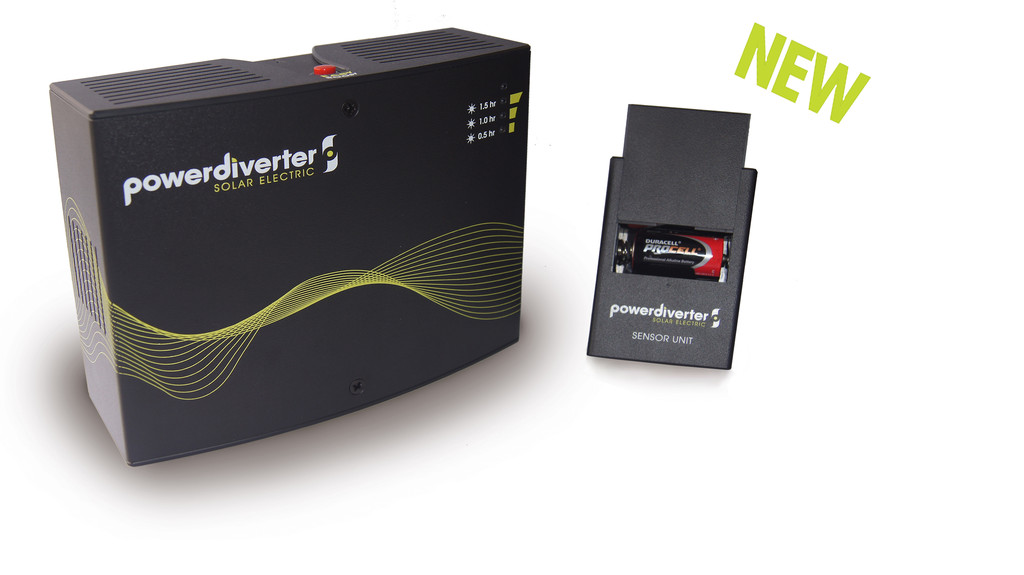
In this picture the small part is battery powered and in my meter box. The large part is by my tank.
In an ideal world I would not add another CT clip and instead just connect from the Pi over RF to the one for the powerdiverter
That was my initial thought, but I then realised that this CT is (I suspect) simply looking to see which way the current is flowing and not actually doing any measurement.
If that “CT” has no connection to the mains, then a measurement (in VA) is all it can do.
(aside from detecting a current-flow / no-flow condition)
Without a mains voltage sample to do a voltage / current phase comparison,
there’s no way to determine the direction of power flow.
In that picture I posted the small box on the right with the battery has a CT Clip and it has a right and wrong way round. It is attached to the mains cable as you can see in the pictures higher up. (reposted below for clarity)
It is the blue clip that is the Powerdiverter.