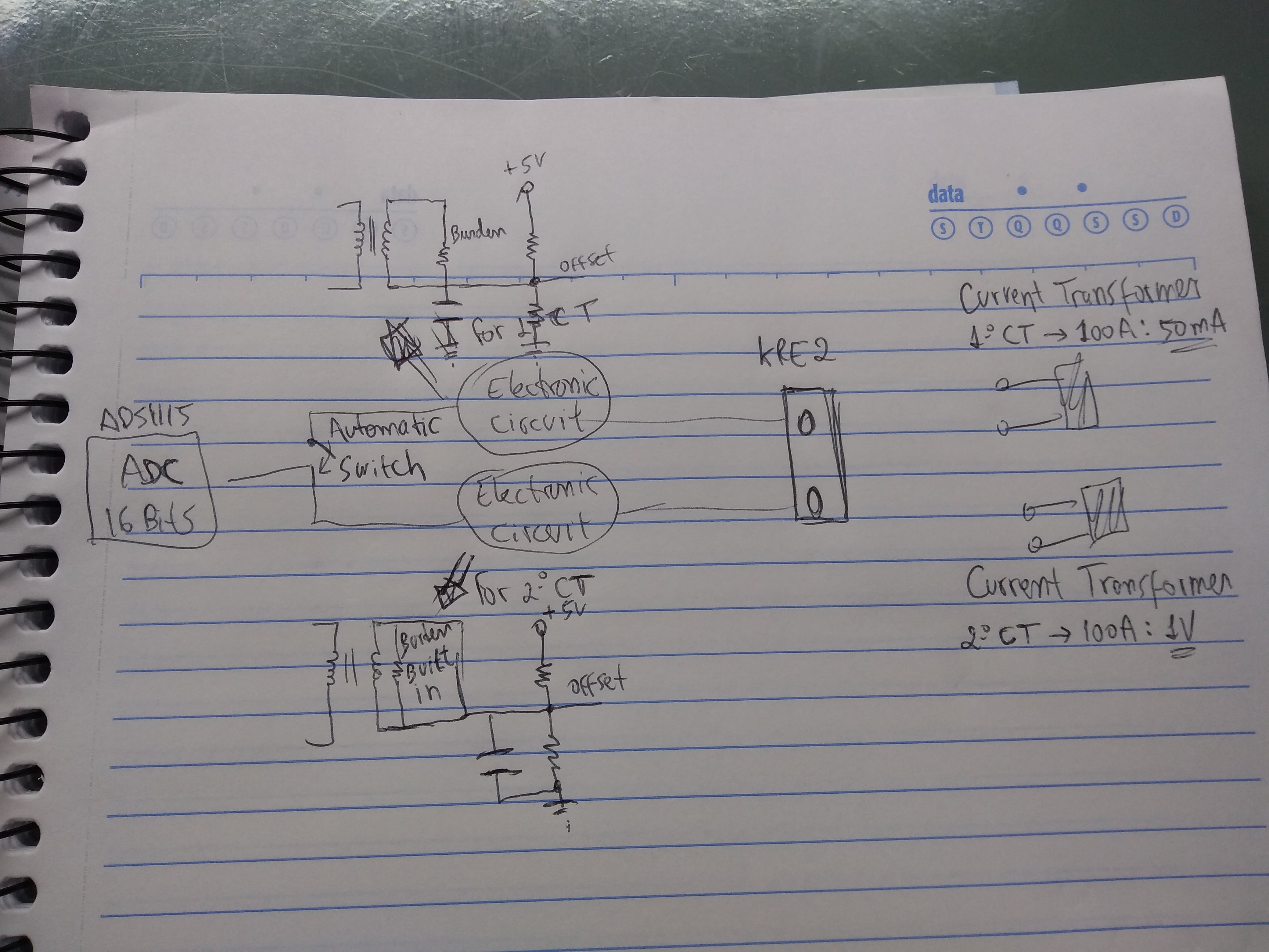
I’ve been beating my brains out in a circuit I attached a figure below. Well I have 2 current transformers(CT). First from current on secondary 100A:50mA and second from voltage on secondary 100A:1V. In my first CT, I need to add burden resistance to measure current on secondary and add an offset of +2.5V because of my ADS1115 (16 bit ADC) Im going to read on its analog input, however for second CT I just need to add offset. About this circuit its done and you can find more info to get update about my following problem:
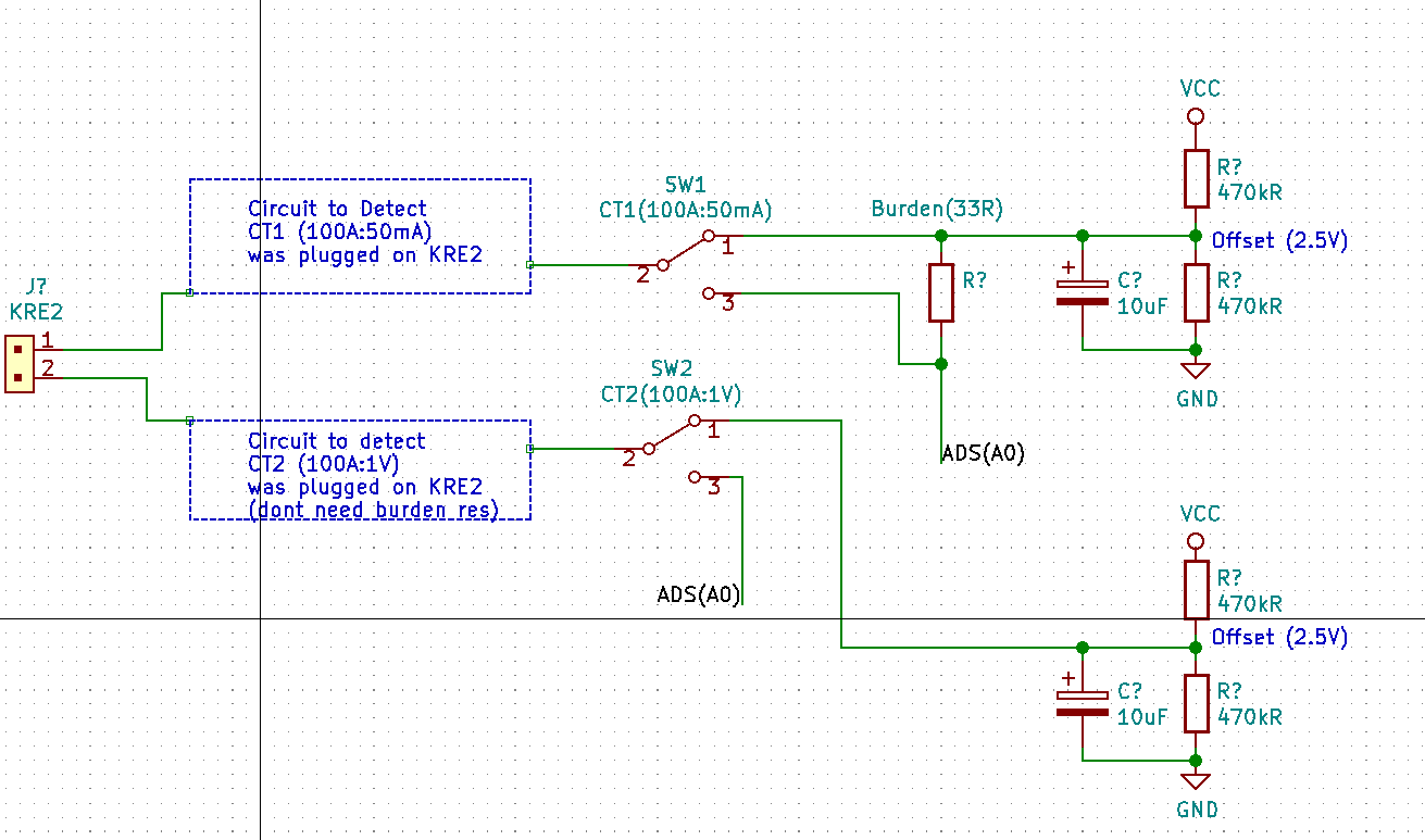
I want to know if is possible to have 1 KRE 2 connector on the board im going to design and when I connect 1º CT (100A:50mA) on my KRE 2 connector I should select its circuit (with burden resistance) and then go to my A0 ADS1115 input while my 2ºCT keep disconnect of course. However, if I wanna plug my 2ºCT on my KRE 2 connector, I need to switch for its circuit and then go to ADS1115. Signal track for ADS gonna have 2.5V because my offset. I just would like to know how to do it automatically if possible just using analog components. Any doubt, let me know
Why do you you want to switch between two different c.t’s?
The way you are connecting the c.t, using our example circuit, you are using only one input of your ADS1115, and you have four inputs available. Why not use one of the other 3 inputs for the second c.t., then in software select the output you want to use?
If you are already using all 4 inputs, I still think it would be simpler to add a second ADS1115 and select between the two SDA inputs to your microcontroller in software.
If you cannot do either of these things, look at Atmel’s Application Note AVR465. That uses analogue switches to change the gain of an operational amplifier circuit. It is not exactly the same as what you want to do, but it is very similar.
Also, look at the data sheet for the Atmel 328P. Inside that is a multiplexer - a switch that does exactly what you want to do - so that will show you how to solve your problem.
Hi, thanks for asnwer. Thats it what u answer but look, I cant welder 100 burden on each CT because Im going to do it on large volume and someone is going to install it for end user, so I need something easier thats why automatic without need changes once im going to buy like 100 CT and send for assembly product and its gonna make very expensive manually modification on CT. Imagine a panel installed and just with KRE 2 connector outside. What I need is just plug CT (being it with burden built inside or not)
and i dont think theres a problem if during 5 seconds after I plug my CT, for instance (100A:50mA) which need burden resistance wait for circuit switch, should have a delay because of course I will need to plug my CT first on KRE 2 and then my circuit detection be able to answer if CT need burden or not and then switch for right circuit as I attached.
Well, let me clarify better what I need again. Im going to measure 3 phase, so I will use A0,A1 and A2 analog input from ADS1115 cause I have better resolution of course than use Arduino ADC or ESP adc thats why external ADC and thats wy ADS1115 (I get 15 bits up to 32768 samples (1bit for start)) and I will leave A3 open (no connect) its for especific application, which is just measure 3 phase current. Im designing a board which gonna work as a shield for main board in my company thats just it. I should hang a voltage sense on A3 but i dont need it.
The idea is I plug ct on KRE 2 (terminal clock yeah, there are blue one and green one) and after it a circuit to detect if the tc have burden inside or not to switch for the right circuit because ct1 (100A:50mA) theres no burden inside, then I need a burden to have a closed loop. However, if its ct2 (100A:1V) it already have burden built inside then I just need offset circuit for ads. Thats what I need. I was thinking about comparator but i dont know if gonna work. Thats where I need help. I need something analogic to switch between SW1 or SW2 depending on which CT I plugged on KRE2. Thats what I need help, please.
If someone have a better idea for circuit topology let me know too, if I can reduce components, for instance.
and Im using a board with Esp8266. Anyway Im powering it with +5V and theres a voltage regulator for 3.3V but what Im doing is just a shield for that board that exist in my company
I still do not understand your problem. Why do you want to use two different c.t’s in your device. One has an internal burden, one does not. Why are you not using the same c.t. throughout? It would greatly simplify your design. It will be the most reliable solution.
First, check your circuit diagram. It is not correct. One side of the c.t. connects to the bias supply, the other side to ADS(A0). And you only need one bias offset supply as you will only use one c.t. at a time.
OK, let us say that you want the complicated and expensive and error-prone solution. The best I can think of is this:
Our standard 100 A : 50 mA c.t. (SCT-013-000) has a resistance of approximately 100 Ω
The 100 A : 1 V variant of that (SCT-013-000V) with the internal burden in parallel has a resistance of about 20 Ω
Your “circuit to detect” needs to measure that resistance - possibly in the presence of an a.c. signal if the user has energised the circuit that the c.t. is measuring, and then operate the appropriate switch. Plus, this detection circuit must not affect the measurement. This is a very complicated problem to solve. The way I would attempt to solve it is to feed a small current through the c.t. secondary winding and measure the voltage - you can use the ADS1115 for this, but you will need two more switches - one to ground the offset bias supply end of the c.t., and the second to connect the d.c. current that will measure the resistance. Having measured the resistance and decided which c.t. is connected, the circuit must disconnect itself so that it does not spoil the measurement accuracy.
I need to say this again: I have been in electrical and electronic engineering for 50 years. The simple, cheap and reliable method is to use one type of c.t. or the other type. Do not mix them.
Hi. Its because company policy here. We found a national CT supplier in Brazil and gonna use it because many factors (low time delivery, he is close for us, etc) however we have yhdc from China but supposing a customer here need to have our product installed next week, wont be possible to have yhdc sct013 within 7 days importing it from China to Brazil(we can have) but wont worth and we are going to reduce profit or have null profit for this approach.
Despite it, company here dont like to import directy from China (many reasons again like high fees, if we have damaged itens need to change, etc). We need to have options for national supplier and international supplier. The idea for next circuit is to use national supplier CT with like 100A:5A because its cheapest one, but there are 100A:1A available for minimun secondary current up to 6000A:5A for instance. What I need in my circuit and avoid is let end user need to switch any push button because they can make mistakes and “destroy” factory, because for instance, forgot to switch manually for CT2 and plugged CT1. That decision is because cheapest price and better logistic to send product to assembly, like 100 units of this product (energy meter) and it means need to buy 100 CT1 (100A:5A) from national supplier 1, 100 CT (100:1V) from yhdc supplier and 100 CT (100:0.33V) from yhdc supplier. We wont buy yhdc sct013 with no burden inside, only with burden inside (output 1V and 0.33V because ADS1115, thats firmware issue not my whole concern in company that im responsable to design hardware)
We considered here buy 100 CT with no burden inside and welder it inside, however it again increase so much costs to do it and again decrease profit or null it, cause will be necessary to send for a assembler factory do it for all 100 sct, cut all p2 plug off cable and let 2 wires to plug in KRE2). I know its better solution just use CT with burden inside but not good for company. Thats a challenge for it.
So I will need to measure 3 phase, thats why 3 sct013 using A0,A1 and A2 input from ADS1115 to have better resolution and firmware guys deal with it better and have like 3% error from measure. This time we only need to measure current and we need these 3 models of sct, 1 national supplier(100A:5A) and 2 china supplier (100A:1V and 100A:0.33V). So china supplier have burden inside its ok, easy to solve. However, national supplier theres no burden inside and as our product gonna be installed inside a factory for instance, we just wanna provide KRE connectors interface for technical people there unplug CT and plug CT without to worry with which CT are going to be used (with burden inside or not). Thats why an automatic circuit to detect if my CT have burden inside then just use my offset circuit and ok or if my CT dont have burden inside, switch for a circuit with burden and then use offset circuit for ADS1115. Its basically this reasons for dont follow your idea for now. Do you think its possible to do what im saying please?
I understand that. I only used the numbers for the YHDC c.t. because I know the values. I expect you will find that your local manufacturer’s c.t. will be similar, for a similar c.t.
I think it might be possible to automatically detect the burden or no burden, but I cannot be certain of that. You must build a prototype and test it. Also, you must use the smallest possible current if you use d.c. to measure the resistance, because you must not permanently magnetise the core of the c.t.
hi, how should I test ct with multimeter? It only work for ac current no? what should happen if I connect a second burden resistance for a ct which already have burden built in, gonna be ok? CT with no burden even If i connect it without burden theres a voltage on secondary because diodes internally? We mustn’t leave open circuit on secondary but what gonna happen for sct013 with no burden for few seconds if I leave it open ? Im asking it because this ct comes with TVS diode internally…
You can measure the secondary current (if you have a suitable a.c. current range).
You can measure the resistance at the secondary winding terminals. From that, you might be able to tell if your c.t. has an internal burden.
Yes, your c.t. will be OK. But you will have a voltage that is approximately half that which you expect, because the c.t. itself is a current source and there will be two burdens in parallel, so there will be the same current into half the resistance, hence half the voltage.
This is where you can destroy your c.t. The c.t. is a current source. It wants to drive a current into the burden. If the burden is a high resistance - and with no burden, the resistance is near to infinite - it will try to generate whatever voltage is necessary to drive the current. If the burden resistance is near to infinite, the voltage will also try to be near to infinite. In the worst case, the secondary winding insulation will break down and your c.t. will be destroyed.
The internal diodes are there to provide a safe path for the current and so limit the voltage to a safe voltage (for humans and for the c.t.). It might not be safe for your ADC and that might be destroyed.
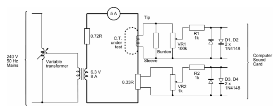
How can I simulate it on ltspice? You guys can help me to understand secondary of this ct? Its because its weird 0.72R I thought only when u have voltage source u need a series resistance and for current source need a parallel resistance to take measurements for a non-ideal sources. So you have 5A current source on secondary, this is what means 5A on diagrama? Another point is why (6.3V 8A) on secondary inductor of ct, where this value came from? Its like if you have sct013-100 (100A:1V) Which difference between yhdc (100A:1V) and (100A:0.33V) in terms of calculations?
You are looking at the diagram of my test rig. The 6.3 V transformer is a voltage transformer, not a current transformer. I use it so that I do not waste a lot of power when testing, and I am handling a safe 6.3 V, not 240 V from the mains. The 0.72 Ω, along with the metering shunt (0.33 Ω), limits the current to a little over 5 A.
That true current signal from the shunt is how I obtain a reference to measure the phase error of the c.t. under test.
I have a few links about Spice transformer models. I have never found the time to customise any of them to the real c.t. that we use.
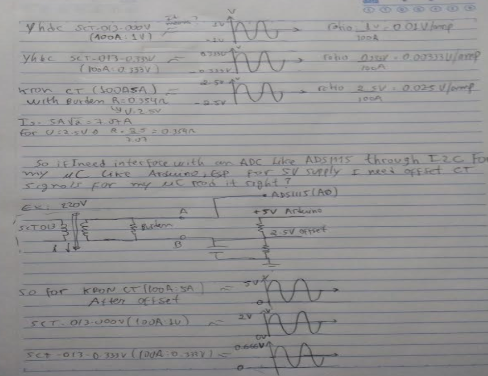
If I have a ct (100:5A) I will have a alternate current of 7.07A on secondary and If I need to convert it to voltage for my uC read it, I will get a 0.354 ohm burden resistance for it. However I would like to know, if possible how much the relation A/V on output. For instance, for a ct (100A:1V) I got 0.01V output for each 1A input.
The voltage across your burden resistor will follow from Ohm’s Law, just the same as for any resistor.
So with your 0.345 Ω burden, you get 1.77 V rms for 5 A of secondary current, which equates to 100 A of primary current. The scaling is therefore 1.77 V per 100 A, or 17.7 mV/A.
I don’t think so. Your c.t. will probably start to saturate at a little over 100 A, almost certainly before 140 A, and the waveform will become distorted and you will never see 7 A secondary current. And the distortion means you will not read the correct current when that happens.
for a (100A:1V) ct what I have is a sine output from -1V to 1V alternating? If I wanna to interface it with a ADC like ADS1115 using I2C with my uC I need to make an offset using voltage divider because my uC dont read negative values. Up to now its ok, right?
So, If I have 3 CTs. I have Ct1 (100A:0.333V) ; CT2 (100A:1V) ; CT3 (100A:5A) I will have outputs I drew ? I calculated for CT3 I need 0.354 ohm burden if I wanna 2.5V output. In this case if I have ADC like ADS1115 which need 5V I should set its scale to 4.096V, right? After my offset I will have alternate positive values?
How can I calculate or know burden resistance for CT1 and CT2 that already have voltage output? Theres any information on datasheet from supplier yhdc.
NO, at the c.t. terminals, you have a 1 V rms signal. If it is a pure sine wave, that is 2.828 V peak - peak. You must add a bias offset to read it with a single-ended ADC (as you are using the ADS1115. It is exactly like the diagram you linked in your first post, where in your case the size of the blue wave is 1 V rms when 100 A rms is flowing. You must add a bias offset of at least 1.414 V so that the negative peaks do not go below 0 V.
I have not studied the ADS1115 data sheet in detail, so I cannot answer questions about that. I am sure that if you read the data sheet, it will explain how to use it.
If you follow our circuit (for the Arduino), you will get numbers representing points on the wave where it is sampled. If your input wave is the maximum possible and goes between 0 V and VDD, these numbers will go from 0 to 216.
Then, in software, you must remove the bias that you added - the mid-point voltage. So you must subtract 215 from each sample to obtain the true wave shape centred about zero.
Why do you want to know that?
The burden converts the c.t’s secondary current into a voltage. You know do not know the secondary current, and you do not know the burden resistance. But that does not matter, the data sheet tells you the voltage.
So for CT1, you know you will have 0.333 V rms for 100 A rms,
for CT2, you know you will have 1 V rms for 100 A rms,
and for CT3, you know you will have 5 A rms for 100 A rms, and 5 A × 0.354 Ω = 1.77 V rms.
You know the voltage, which is what the ADS1115 measures, for each c.t. when you have 100 A. You do not need to know any more.
No, I have not opened one, I don’t know what the value is, and there is no need to know the value. Knowing the value does not make any difference to how your circuit will work, nor how you calibrate it.