I have three phase 230v IT setup in my house. I don’t want to use EmonTx to measure the energy of the whole house, but a few circuits (water heater, washing machine, etc). Will the fact that I have three phase affect me? The AC-AC-adaptor is on L1/L2. If I clamp on a CT on a wire on L3, will it just assume the same voltage and give an reasonable measurement? Or will it cause problem that I have no vrms-measurement from L3?
First question: which 3-phase system exactly do you have? As I understand, you have a “3-wire” system at 230 V line-line, and no neutral connection, so you measure approximately 132 V from any line to earth. Can you confirm that, please?
If that is the case, then as long as you are measuring the same voltage and the same current that the appliance - or group of appliances - sees, then you do not need a 3-phase sketch, nor the “3-phase 3-wire” sketch (not on Github, and which I need to rewrite using the “PLL” technique to improve the accuracy) which is better for a 3-wire system. What you will really be doing is treating L1 or L2 (it does not matter which) as the neutral as far as the measurement is concerned, and then you have a single-phase system. You only have a problem when you measure a current where part of that current finds its way to L3.
Yes, 132v between phases and earth.
A 230v IT setup: http://www2.schneider-electric.com/documents/technical-publications/en/shared/electrical-engineering/electrical-networks/low-voltage-minus-1kv/ect178.pdf
If I understand correctly, as long as I don’t clamp a ct on phase 3, the measurements will be correct?
Not necessarily. I wrote “You only have a problem when you measure a current where part of that current finds its way to L3.”
By that I meant that those circuits (water heater, washing machine, etc) must be connected L1 - L2, and you must put the c.t. between those loads and anything else, so that you only measure the current that flows between L1 & L2 via those appliances. That part then behaves as if it is a single-phase system, and the standard emonTx sketch using the a.c. adapter and one c.t. per circuit will be all you need.
If you cannot do that, then you will need me to convert the 3-phase 4-wire sketch into a 3-phase 3-wire sketch for you.
Unfortunately, the fuses are evenly spread between L1/L2, L1/L3 and L2/L3 so I won’t be able to only measure on a L1/L2 circuit. If you could modify the sketch, that would be awesome! ![]()
We are talking about the emonTx V3.4?
I take it then you’ll be using the different c.t. inputs on different loads, which may be connected between any 2 phases.
I hoped that would not be the case, but I feared that it would be.
OK, I’ll see what I can do. You will almost certainly have to wait for a little while.
Yes, brand new. ![]()
Yes, plan on using 4 C.T.s, clamped to 4 different fuses.
This is the most common setup I Norway until 1997, but I think Norway is one of few countries with this kind of circuit…?
Sounds great! ![]()
If I in the meantime hook on to a L3-wire, what will be the result? No measurement? Or inaccurate measurements?
That is my understanding too - but you know, you are there! I learned recently that there are some isolated examples in (I think) France and Belgium, but generally Europe except the UK is 3-phase, 4-wire, 230 V L-N. The UK is historically 240 V L-N, with only industry and large commercial buildings being 3-phase, private homes are almost universally single phase.
How good are you with phasor diagrams?
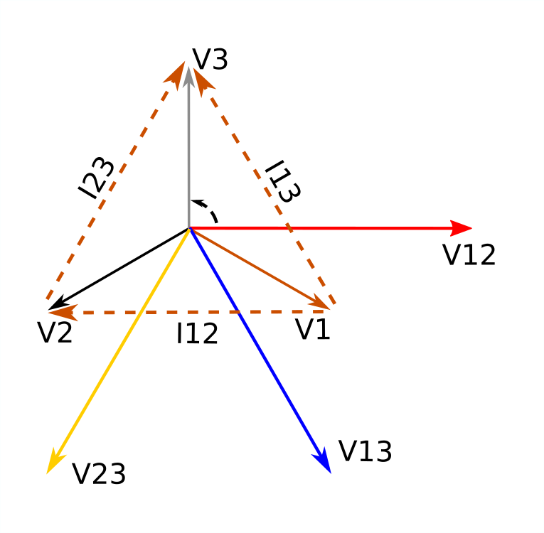
This is what you have.
V1, V2 & V3 are the line voltages to the star point (maybe earth). The voltage you measure is along the Real axis (x), V12.
The voltages the sketch needs to synthesize in order to measure the real power in loads connected between L1-L3 & L3-L2 are V13 & V23, and they are 60° & 120° displaced. The 3-phase sketch on GitHub displaces those by 120° & 240°. You could actually use it, because 60 = 180 - 120 (and 180 means flipping the c.t. round on its wire) but the bigger snag is the c.t. inputs 2 & 3 are dedicated to lines 2 & 3, only input 4 can be freely allocated to any line.
You can try it if you wish. If it so happens that the things you want to measure are one connected L1-L2, one L2-L3, one L3-L1 and the fourth can be any of these, then it will work for you.
I’ve quickly looked at the 3-phase, 4-wire sketch to refresh my memory, and it would appear that it’s a relatively simple job to add in support for your 3-phase, 3-wire system with free allocation of the c.t’s to the various connections.
I hope I’m right. But I think you will need to test it, because I don’t have access to a 3-phase supply of any sort.
I took a year with basic electrics/electronics 15 years ago - seems I need to pull out my old books, 'cause this is completly forgotten!
That sounds great! ![]()
In your prev.post, I got the understanding that ct1-3 was only meant to measure the mains, not individual fuses, but now you say that my intended use will be possible after all?
No problem, I bought a USB-TTL-programmer and have experience with Arduino/ESP8266, so uploading a new firmware should be no problem. ![]()
Correct on both counts. I’ll make it so that you specify where you use each c.t.