Three phase & solar setup help

Hi,

I have recently purchased and setup some emon gear and clearly need advice on how to set it up correctly. I have an emonpi and 2 x emontx. I purchased plenty of CT clamps (one for each device input) which is probably too many. When I ordered them, I requested both emontx be supplied with the three phase firmware and each has a unique nodeID.

I’m in Australia and have three phase mains power and also three phase off-peak/controlled load for in slab heating (both three phase setups have their own smart meter). I also have a 10kW solar system with two Sunny Boy inverters.

When I was ordering my emon gear I assumed that I needed the following:
1 x emonpi to monitor the Solar inputs - two CT’s (one to monitor each inverter)
1 x three phase emontx to monitor the main three phase usage - 4 CT’s (to monitor each of the three phases + neutral)
1 x three phase emontx to monitor the off-peak three phase usage - 4 CT’s (to monitor each of the three phases + neutral)

I was hoping to sum:

  • the two solar inputs to give the total solar generation
  • the three mains phases to give the total mains usage
  • the three off-peak phases to give the total off-peak usage
  • total mains usage + total off-peak usage to get total household usage

The goal was to feed the above data into the local emoncms My Solar App to provide a view of current use, solar generation and thus how much we were importing.

My electrician has kindly drawn up the attached diagram for me to help me get a view of the meter box wiring. As an initial start we have added the CT clamps as shown in the diagram.

I am getting readings from the CT’s but the numbers seem very low for both usage and solar generation.

To start simply, the other day the two CT’s that are monitoring the two solar feeds were showing a combined total of 410w:

At that time, the two inverters were showing 715w and 826w each:

I did see the Type 1 and Type 2 sensor installation diagrams (here Solar PV - Guide | OpenEnergyMonitor) but I don’t understand how they relate to my multi-three phase and solar wiring.

I am really unsure how I should be setting up the CT’s and I’m hoping the community can offer some guidance on the right way to setup my system.

OK, I’ll try my best. On the basis that your diagram uses red for the three phase conductors and blue for the neutral…

You bought two c.t’s too many. A c.t. on the neutral will only tell you the vector sum of the three phase currents - which doesn’t mean much to you. Ideally, when everything is balanced across your three phases, that current should be zero. You’d have saved some money if you’d asked first.

The PV infeed is single phase - is that correct?
Are there four cables there, or two twin cables? If you put your c.t. around a twin cable containing both line and neutral conductors (see the photo on that page you link to), you will not read anything except noise. What are the individual powers, and how do they relate to the inverter displays?

You don’t mention a.c. adapters? Do you have an a.c. adapter for each emonTx and for the emonPi? The a.c. adapter is absolutely essential for the emonTx’s, without it the software cannot lock to the mains wave and so cannot measure the powers. You might be able to get away without an a.c. adapter for the emonPi, but what you measure will be a best guess at the apparent power, based on an assumed constant value for the voltage, not the real power.

Have you read the documentation that comes with the 3-phase sketch and set up the emonTx’s according to that? Update to 3-Phase PLL sketch - #21 by Robert.Wall .
I take it you didn’t buy a programmer, so you won’t be able to make any changes to the software.

If your diagram is accurate, i.e. you are measuring the house consumption on the house side of the point where the PV is connected and you’re measuring the PV input entirely separately, you have a “Type 1” set-up.

If you were to move the three c.t’s so that they are on the grid side of where the P.V. connects, you would have a “Type 2”.

The names “Type 1” and “Type 2” are OEM’s own, and relate to the values you know and how you arrange the equation [Total Use] = [Grid] + [PV].
In a “Type 1”, you measure [Total Use] & [PV], and derive [Grid].
In a “Type 2”, you measure [Grid] & [PV], and derive [Total Use].
Note, we measure imported, used, and P.V. generated powers as positive.

In terms of the diagram, you must sum the set of three phase powers measured at “Main Sw house” to get [Total Use] or (power1) in the description, as a single Feed; and likewise sum the two PV powers to get [Total PV] or (power 2) before you can use them in emonCMS “My Solar”.

Hi Robert, thanks very much for the reply. I really appreciate you taking the time to comment. I’ll answer your questions and add some additional info below.

CT’s
I’m ok with having bought some additional CT’s since I was ordering from the UK I figured I’d have a couple of spares if they weren’t specifically needed in the first instance. I hadn’t asked prior to purchase because I hadn’t had a chance to understand how the wiring was setup in my meter box at that time. It was only at the time of first installation of the CT’s that I and my electrician could review the wiring setup.

Based on the diagram from my electrician it looks like both inverters are tied into a single feed. I’ll have to check with him for more technical info. Its seems like that feed is only offsetting a single phase which I imagine can’t be very effective since I’ll just be pulling power on the other two phases (and all three phases of the offpeak meter). I will need get him out to review the CT clamps for correct placement and directions.

AC Adapters
Thanks for mentioning the a.c. adapters. I do have an a.c. adapter for each device - one for each emontx and one for the emonpi. I also have a USB power supply for the emonpi.

3-Phase Sketch
Regarding the 3-phase sketch, I specifically mentioned in my order that the two emontx devices would be used to monitor three phase power and requested that both devices be loaded with the required 3-phase configuration/sketch.

You are correct, I didn’t buy a programmer as I’m hoping they have been loaded with the correct 3-phase sketch. Is there a way to identify the type/version of the sketch contained on each emontx?

When viewing the Emoncms Inputs, I can see that I am reading data on the 3phase and 3phase2 node id’s (as well as the emonpi):

image

I was hoping that indicated that the emontx devices are configured with the 3phase sketches. Would this be correct?

Calibration
Is there any configuration/calibration I need to do in the web interface such as describing what CT’s are being used?

Type 1 vs Type 2 Set-ups
Thanks for describing the differences between the Type 1 & Type 2 set-ups. If I understand it correctly, I’m definitely keen to use a Type 1 set-up as I would like to measure the actual use rather than derive it. This is due to having the two sets of three phase wiring (one for main use and one for the in slab heating) and I would like to be able to measure them separate to each other. I appreciate that I will need to sum the 6 inputs together to get the household [Total Use] for the My Solar graph, but I would like to also be able to sum the three in slab heating inputs to be able to better monitor the (very) high draw of that system. If I use a Type 2 set-up I could only derive the a single value [Total Use].

The in-slab heating is turned off at the moment so I’m not currently factoring that into my equations but will add it in when I have everything set up correctly.

Inputs and Feeds
It took a lot of reading of other posts to understand how to sum the three inputs together so hopefully I have it setup correctly.

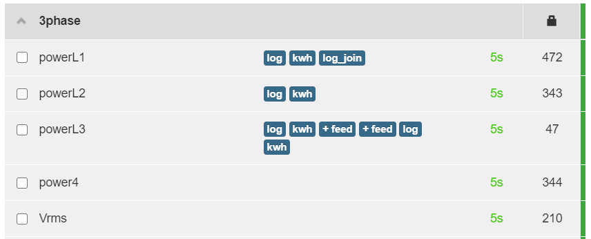
I have the following processes setup on my Main 3-phase inputs:

Showing the powerL3 process list:

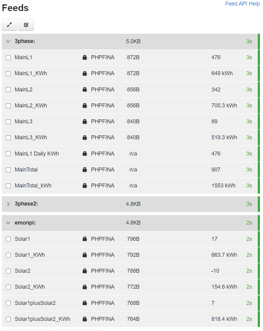
Currently I have the following Feeds configured:

My Solar App
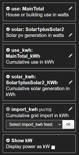
Based on the feeds shown above, I have configured the following settings in the My Solar app:

Negative values
On the day we installed the CT’s I had not had any experience yet with actually using Emoncms. I had looked at some youtube videos and lots of screenshots. When my electrician connected all the CT’s I was reading some negative values on some of the inputs. My electrician was confident that he had installed all the CT’s with the arrows pointing consistently in right direction but we were in a bit of a rush at the time. I assumed that all the values we were reading should be positive so I asked him to change the direction of some of the CT’s to ensure we had positive readings. As a result it’s possible that we have some of the CT’s currently clamped the wrong way around. I need to get my electrician to come out when we have more time and change them so they are all consistent. I feel this was my biggest rookie mistake. :slight_smile:

Device Templates
As I was preparing this response I was browsing the Emoncms web interface and noticed the cog on the far right of each Input node id. I clicked on the cog icon for the 3phase node id and saw that a Device Template can be configured for each device. I had not previously assigned a template for each device but was using the default Input names that came with each device. If I assign device templates now, I assume that will reset the Input names and I’ll need to redo the input processes for the new inputs and recreate my Feeds with the new input names? It wouldn’t be a big deal if I had to do that. Are there any other configuration benefits to applying a device template other than creating default meaningful input names?

Thanks again for your input and knowledge, I hope the above makes some sort of sense.

Not necessarily. The UK rules state that an electronic meter should work in the same way as a mechanical (Ferraris) one, so that it records the nett energy flow across the 3 phases. Your supplier might have different rules, however.

Placement is important. Direction can be done with a minus sign in the software.

Not without a programmer, unfortunately.

They probably are, in that case. But there are many internal options that should have been reviewed, that’s why I won’t publish a “compiled” sketch. If others do that, I can’t know what particular set of options and calibration settings have been used.

Yes, but you need a programmer for that.

I’ve just realised that you’d drawn your diagram upside down - or at least part of it - and I’d misread it. So you actually have two infeeds (that aren’t shown) coming up from the bottom of the page into the meters? (Conventionally, we draw those diagrams as if electricity is water - it flows downhill :grin:) If yes, I was wrong - you have a type 2.

Once the individual c.t. inputs are in emonCMS, all the rest is maths, so you can sum them to whichever “Feeds” (our word for the data you store and display) you want.

I don’t know what those are - they appeared recently and I can’t play with emonCMS to find out because I’m running long-term reliability tests.

I am also setting up a Solar Monitoring system with emonCMS and Sunny Boy inverters. Just to be aware that you can get data from the inverters using Modbus TCP and Node-RED. I have this running on the emonPi as well.

We will be figuring out how to inject this back to emonCMS, but besides AC power, you can also track other data like DC Voltages from your array.

You need to log in to the Inverter as an installer and enable Modbus in the communications menu. The two Modbus registers are 30513(x4) for Wh and 30775(x2) for W on the SMA Inverters.

1 Like