Continuing the discussion from EmonTX to Rpi - Direct Serial Connection:
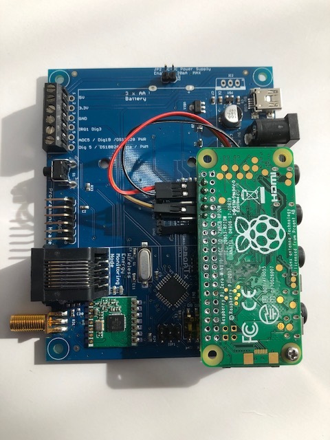
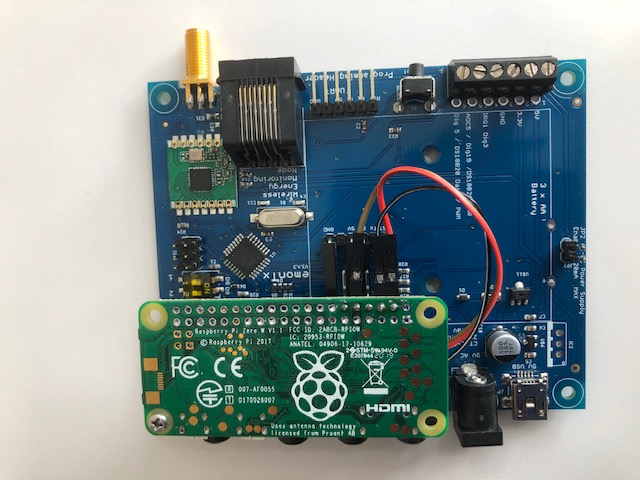
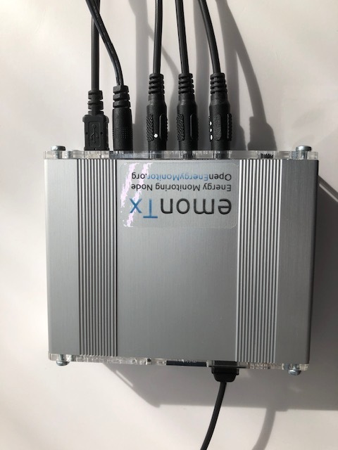
Just thought I’d share another way to put together a 4ct version of an emonPi using an emonTx and a RPi Zero W.
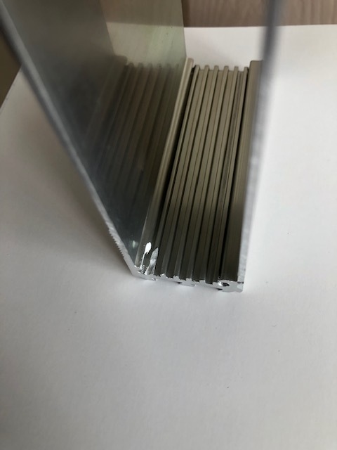
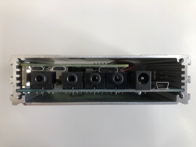
The perspex/acrylic end caps on the emonTx case, combined with orienting the Pi Zero with its PCB aerial against the perspex ‘window’ in the case and the convenient PCB spacing means that the wifi signal still works sufficiently well for possibly most (?) applications. I haven’t bothered checking dB figures but the signal icon on the router it connects to for testing shows full signal with the router downstairs and horizontally more than 5m away from the emonTx.
The only modifications required are:
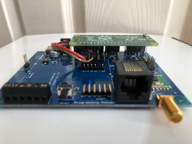
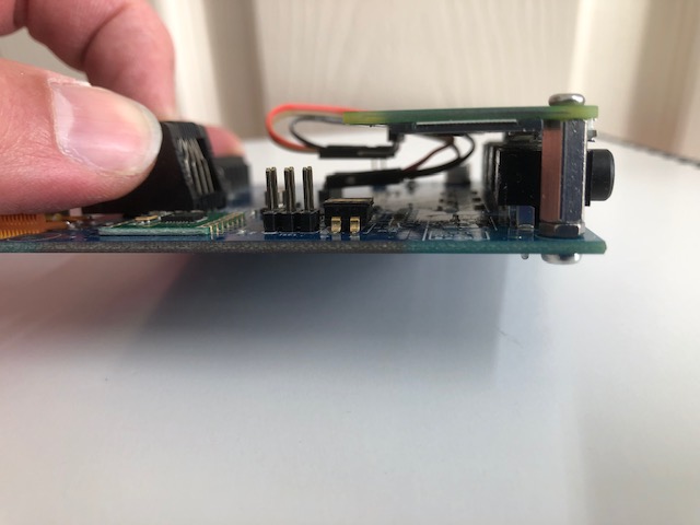
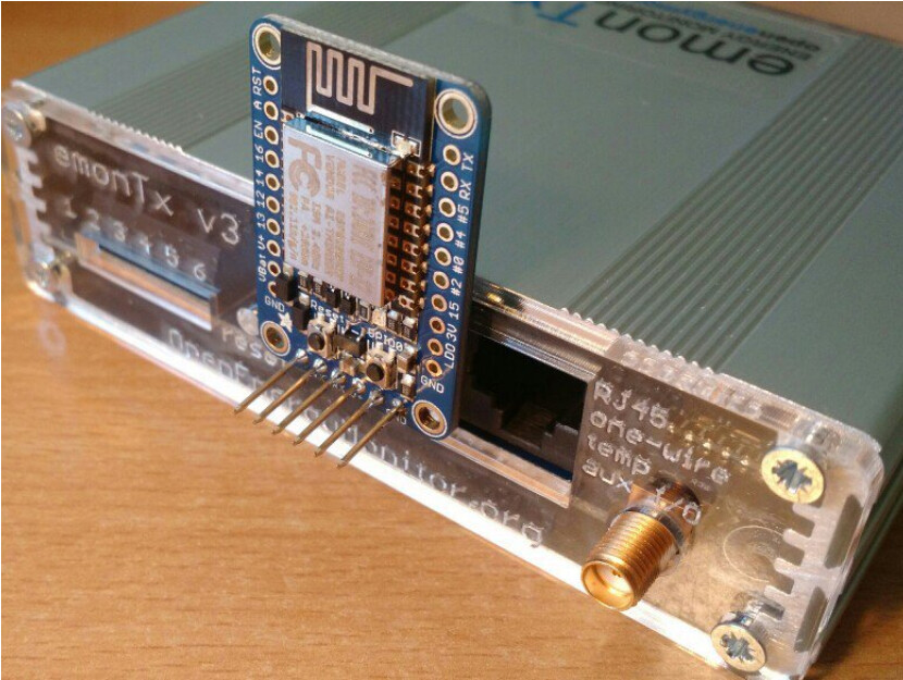
- adding right angle dupont headers to the Pi and to the unpopulated UART through-hole pads in the middle of the emonTx PCB
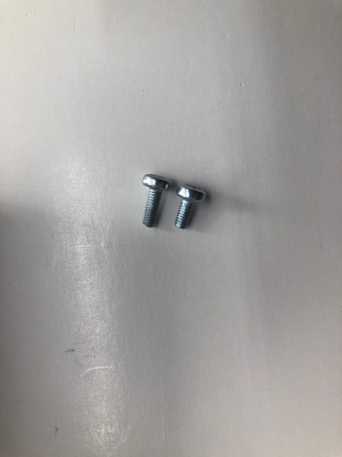
- replacing one of the screws attaching the plastic end cap to the case with a slightly longer one
- Shaving off a tiny bit of the inside corner of the case to clear the standoff screw head on the RPi PCB.
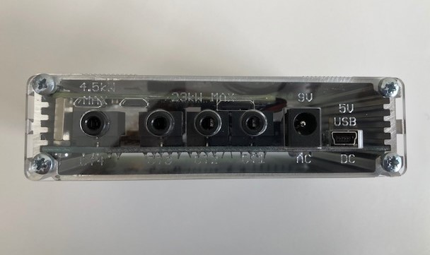
I haven’t managed to get avrdude-pi firmware programming working yet, so have only connected the Rx (sic) pin on the emonTX to the Rx pin on the Pi along with 5V and Gnd (Pi is powered by mini-USB DC supply for emonTx).
This means I think that I should still be able to program the emonTx firmware via the FTDI programmer through the UART port on the back of the emonTx, so long as I remember to shutdown the Pi correctly before pulling power to the emonTx after updating firmware (and discard gibberish data received by the Pi on its UART serial port during updating).
Annoyingly there’s a second standoff hole in the emonTx PCB that almost lines up with the diagonally opposite standoff hole in the Pi Zero PCB I’ve used, but given it’s all protected inside the case, the CT port cases support the Pi quite well and the whole thing will be mounted stationary to a wall, I think one standoff will be perfectly sufficient.
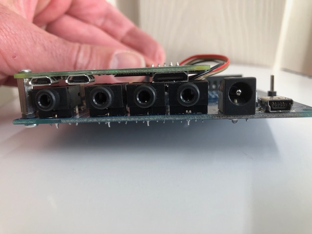
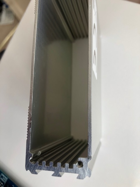
You have to get the standoff height exactly right so that the plastic locking mechanism on the Pi camera connector slides into one of the PCB grooves in the aluminium case, or it won’t all fit together too.