Hello I have been working on an analog temperature sensor TMP36 and I am trying to get the temperature and display it on the NEXYS3 SSD. I am aware the NEXYS3 does not have an analog pin and I built an analog to digital converter using the TI ADC0804 an 8-bit ADC. The part I need help with is particularly getting the input from the temperature sensor. I do not understand the data sheet well enough to come up with the formula in verilog. The only example I found was for an arduino in the link below:
http://www.kynix.com/Search/TMP36.html
DATA SHEET
GENERAL DESCRIPTION
The TMP35/TMP36/TMP37 are low voltage, precision centigrade
temperature sensors. They provide a voltage output that
is linearly proportional to the Celsius (centigrade) temperature.
The TMP35/TMP36/TMP37 do not require any external
calibration to provide typical accuracies of ±1°C at +25°C
and ±2°C over the −40°C to +125°C temperature range.
The low output impedance of the TMP35/TMP36/TMP37 and
its linear output and precise calibration simplify interfacing to
temperature control circuitry and ADCs. All three devices are
intended for single-supply operation from 2.7 V to 5.5 V maximum.
The supply current runs well below 50 µA, providing
very low self-heating—less than 0.1°C in still air. In addition, a
shutdown function is provided to cut the supply current to less
than 0.5 µA.
FUNCTIONAL BLOCK DIAGRAM +VS (2.7V TO 5.5V)
SHUTDOWN VOUT
TMP35/
TMP36/
TMP37
00337-001
Figure 1.
PIN CONFIGURATIONS
1
2
3
5
4
TOP VIEW
(Not to Scale)
NC = NO CONNECT
VOUT
SHUTDOWN
GND
NC
+VS
00337-002
Figure 2. RJ-5 (SOT-23)
1
2
3
4
8
7
6
5
TOP VIEW
(Not to Scale)
NC = NO CONNECT
VOUT
SHUTDOWN
NC
NC
+VS
NC
NC
GND
00337-003
Figure 3. R-8 (SOIC_N)
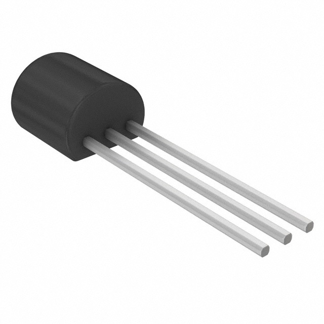
1 2 3
BOTTOM VIEW
(Not to Scale)
PIN 1, +VS; PIN 2, VOUT; PIN 3, GND
00337-004
Figure 4. T-3 (TO-92)
The TMP35 is functionally compatible with the LM35/LM45
and provides a 250 mV output at 25°C. The TMP35 reads
temperatures from 10°C to 125°C. The TMP36 is specified from
−40°C to +125°C, provides a 750 mV output at 25°C, and
operates to 125°C from a single 2.7 V supply. The TMP36 is
functionally compatible with the LM50. Both the TMP35 and
TMP36 have an output scale factor of 10 mV/°C.
FEATURES
Low voltage operation (2.7 V to 5.5 V)
Calibrated directly in °C
10 mV/°C scale factor (20 mV/°C on TMP37)
±2°C accuracy over temperature (typ)
±0.5°C linearity (typ)
Stable with large capacitive loads
Specified −40°C to +125°C, operation to +150°C
Less than 50 µA quiescent current
Shutdown current 0.5 µA max
Low self-heating
Qualified for automotive applications
APPLICATIONS
Environmental control systems
Thermal protection
Industrial process control
Fire alarms
Power system monitors
CPU thermal management
I am powering the ADC with 5 volts and need help converting their formula to verilog.
Voltage at pin in milliVolts = (reading from ADC) * (5000/1024) Centigrade temperature = [(analog voltage in mV) - 500] / 10
Those are the two formulas I need help with. I need an formula equivalent in Verilog. The output to the SSD is an 8-Bit number in other words am only interested in temperatures 0-99 for my project. Thanks any help would be appreciated.